Abstract
UCE Int. Pvt. Ltd. had been my chosen workplace for Internship Program. I had been working in the organization from 8thOctober to 8th December, 2011. I was assigned as a trainee in the RF Survey to setup the network of GrameenPhone. I was under a Senior RF Engineer and had the full scope and independence to work on the project our project name was “GrameenPhone Drive Test Project”. While working on the project I had the scope to come cross many new thing of the Telecommunication system. This report contains all the information about my work experience with UCE Int. Pvt. Ltd. which starts its operation in Bangladesh from 2006.With in this period UCE work with All Telecom Operators and as also with Vendors. In UCE I have spent a superior time in learning and was content for my efforts, learning and performing. I had the experience of corporate and reporting working environment which affects an employee performance and approach to work, had good time in learning and performing. I had the opportunity to work in practical field. So sometimes I had to deal with harsh situations which RF Engineers experience. For better understanding of the program, we sometimes assigned by my project supervisor to do some study.
Company profile:
UCE was incorporated in 1998 in Malaysia. Today, they have four operational offices in Kuala Lumpur, Hong Kong, Surabaya and Bangalore with headquartered office in Kuala Lumpur to support our on-going projects in different countries. Their core expertise is providing Cellular Network Engineering, Consultancy and Project Management Services for Cellular Network Operators, Equipment Vendors and System Integrators in the wireless telecommunications industry.
As in Bangladesh UCE has started its operation in Bangladesh from 2006.UCE technical team is comprised of fully qualified professionals with extensive knowledge, hands-on experience and expertise in the field of cellular engineering. With the experienced management team and a highly competent technical team, UCE will be able to provide optimum solutions to meet the customer demands in this dynamic industry environment
Our Mission:
UCE offers four main categories of services to wireless telecommunications industry – Network Design & Optimization, Network Deployment, Network Auditing & Consultancy and Network Benchmarking. Our end-to-end services are all supplemented with complete program and project management expertise to ensure every service will result in good quality deliverables. Our expertise covers most Technologies in the world now, ranging from different voice switched networks to packet switched networks, namely GSM, GPRS, EDGE, CDMA and UMTS networks.
Network Design and Optimization
In this service, UCE will provision and allocate engineering resources within your company’s network design and optimization organization. With strong experience in Network Design and Optimization, our expertise will not only help spend up your network deployment but also, will provide on-job training and know-how knowledge transfer to the local engineers.
Network Deployment
This is a turnkey solution. UCE will take full responsibility in network design, optimization, acceptance and project management. With our strong technical expertise and different operation in different countries, we are able to leverage different expertise and ramp up or down project engineering resources easily to meet project requirement. You can be sure to have a good quality network launch
Network Auditing and Consultancy
A mature network with the aggressive growing traffics requires network detailed analysis, good expansion and long term strategy planning. In this service, we provide top consultants with at least 15 year experience in the technologies. Our consultants will audit the network from different aspects from technical to market analysis till long term network expansion strategy.
Network Benchmarking
Network Benchmarking is an exercise to simulate the mobile users’ perception or to understand the network performance against other networks’ competitors. Different equipment vendors have different statistical formulas and measurement sensitivities. It is no other fair quality indicators except using network benchmark data to compare the network qualities. This exercise will deliver a report to pin-point the network strength, weaknesses and recommend the possible solution to resolve the network quality issues.
Technology:
- GSM
- GPRS
- EDGE
- TETRA
- UMTS/WCDMA
- CDMA
GSM:
Global Standard for Mobile Communication. GSM is a 2G technology after the pure analogue systems. This technology is a TDMA based system with eight time slots per frequency channel. A normal speech call uses one time slot; audio is typically transmitted on one time slot per frame. Each base station provides a base channel with basic information about the network and the base station in the first time slot of a carrier.The original GSM bands are designed at 900 and 1800 MHz but were complemented in the USA by a 1900 MHz band and the 850 MHz that was originally reserved f or analogue AMPS.
Frequency planning on the network side is critical to avoid interference and dropped calls. Interference with neighboring cells can be minimized through GSM features such as power control, DTX and frequency hopping.
GPRS:
General Packet Radio ServiceGPRS was designed to overcome the limitation of GSM technology on data traffic. It supplements today’s Circuit Switched Data and Short Message Service. Theoretically, it can support data speed up to 171.2kpps by combining all eight timeslots at the same time. This is about three times as fast as the data transmission speeds possible over today’s fixed telecommunications networks and ten times as fast as current Circuit Switched Data services on GSM networks. By allowing information to be transmitted more quickly, immediately and efficiently across the mobile network, GPRS may well be a relatively less costly mobile data service compared to SMS and Circuit Switched Data.
The physical layer now consists of four coding schemes (CS), which may be utilized for either the downlink (forward link) or the uplink (reverse link).
EDGE:
Enhance Data Rates for Global EvolutionEDGE is an expansion of the GSM/GPRS protocol to support higher data rates. This is accomplished by utilizing 8-PSK (8-Phase Shift Keying) modulation technique and modulation coding schemes at the physical layer. This modulation provides an increase from 1 to 3 bits per symbol, thus improving the overall data throughput. The physical layer now consists of nine modulations coding schemes (MCS), which may be utilized for either the downlink (forward link) or the uplink (reverse link).
TETRA:
Terrestrial Trunked RadioTETRA is a TDMA standard, similar to the GSM standard. It uses four timeslots per carrier; the carrier bandwidth is 25 kHz. Similar to GSM, the first timeslot on the first Carrier transmits the BCCH, a logical channel that bears synchronization and control data.TETRA uses π/4 DQPSK (Differential Quaternary Phase Shift Keying). This modulation is highly efficient with spectrum resources, but requires high linearity of all RF components, especially the RF power amplifiers in the radios.The TETRA services are based on three major service classes with different air interfaces, all specified by ETSI:
- Voice plus Data (V+D), circuit switched speech and data transmission, (ETS 300 392)
- Packet Data Optimized (PDO), data traffic based on packet switching, (ETS 300 393)
- Direct Mode (DMO), a simplex voice transmission between two mobiles without using a network. On a physical channel two simultaneous DMO calls can be established. (ETS 300 396)
UMTS/WCDMA:
Universal Mobile Telephone System/Wide Band Code Division Multiple AccessWCDMA is a 3G technology after GSM. This technology is designed based on the CDMA system. CDMA stands for code division multiple access. This means that the available frequency channel is broken down by different code sequences that are multiplied by the user signals of the individual subscribers. All subscribers transmit on the same frequency and at the same time.For WCDMA different base stations are distinguished by a different scrambling code, which makes cell planning a lot easier, since neighboring cells can re-use the same frequency! (However, the occupied “SNR” – or Signal to Noise Ratio is the limiting factor and characteristic for CDMA.
CDMA:
Code Division Multiple AccessCDMA is a “spread spectrum” technology, allowing many users to occupy the same time and frequency allocations in a given band/space. As its name implies, CDMA assigns unique codes to each communication to differentiate it from others in the same spectrum. In a world of finite spectrum resources, CDMA enables many more people to share the airwaves at the same time than do alternative technologies
Introduction
GSM network consist of different cells and each cell transmit signals to and receive signals from the mobile station, for proper working of base station many parameters are defined before functioning the base station such as the coverage area of a cell depends on different factors including the transmitting power of the base station, obstructing buildings in cells, height of the base station and location of base station etc. The Drive Test (DT) perform in RF optimization GSM network to assure the availability, integrity, & reliability of the network.
Drive test
Drive-testing plays an important role in creating and maintaining a strong GSM network. In mobile communication system drive testing should be used to collect real-time RF information from the field. Generally this is done using a vehicle, but it can also be carried out on foot where circumstances dictate (like inside a building for IBS Testing).In any case, keeping mobile phone network optimized is vital. Changes in the environment continually affect network performance. Operator can’t afford to have unhappy subscribers because there are holes in their coverage or because interference is causing dropped or blocked calls. To migrate to new technologies and applications operators need a drive-test system that will expand with their needs.
The Purpose of Drive Testing
Drive testing is principally applied in both the planning and optimization stage of network development. However, there are other purposes for which drive testing can be used:
- To provide path loss data for initial site survey work
- To verify the propagation prediction during the initial planning of the network.
- To verify the network system parameters.
- To provide the initial test parameters used in Benchmarking.
- To verify the performance of the network after changes have been made e.g. when a new TRX is added; the removal or addition of a new site; any power adjustments or changes to the antenna; any changes in clutter or traffic habits.
- To measure any interference problems such as coverage from neighboring countries.
- To locate any RF issues relating to traffic problems such as dropped or blocked calls.
- To locate any poor coverage areas.
- To monitor the network against a slow degradation over time, as well as monitoring the network after sudden environmental conditions, such as windstorm or electrical storms.
- To monitor the performance of a competitor’s network.
When to Drive Test
Drive testing can take place during the day or at night and is dependent upon the Operator’s requirements and subscriber habits. Drive testing during the day will imitate the conditions as seen by subscribers, but may clog up the network if call analysis is being performed. Drive testing during the night will allow a greater area to be surveyed due to the reduction in vehicular traffic jam. It will also allow for certain test signals to be transmitted and tested, particularly when setting up a new site, without interrupting normal operation. However, night-time testing does not imitate the conditions experienced by subscribers. For planning purposes, drive testing is typically performed at night and for maintenance purposes, drive testing is performed during the day.
Where to Drive Test
Some areas of a network will have greater performance problems than others. Drive testing should not be regular throughout the whole network, but should be weighted towards areas where there are significant RF problems. There may be other areas of the network that require temporary coverage during a certain time of the year e.g. an exhibition centre or a sports stadium. These areas should be examined and planned in greater detail. Sometime operators can perform drive test for their customary check for a certain city or some specific clusters of a city.
Types of drive Test
Drive test can be performed in very many ways. Different types of drive test fulfill different types of requirement from the customer.
- Single site Drive Test
- Cluster Drive Test
- Acceptance Drive Test
- Site Swapping Drive Test
- Benchmarking Drive Test
- Functionality Test
- Walk Test for IBS
Tools (Drive Test Kit)
Drive testing needs some distinctive type of tools, like some special mobile phones and software. The followings are list of tools generally required for drive test:Hardware:1. Drive test vehicleFour wheeler vehicles are perfect for drive test to access important but tough access roads or muddy roads.2. Power InverterThis device inverts DC power to AC power. We can use it to invert vehicle’s DC power to AC power to ensure uninterrupted power supply to the laptop and other electronic devices during DT.3. Laptop computerDT laptop should be with good condition and configuration, like high speed processor and especially RAM volume should be more for smooth drive testing.4. Mobile phones and phone chargerSpecial mobile phones designed with field measurement features. How many mobile phone should we use during DT depends on the types of DT. Some testing requires one phone and some other requires two or more. Chargers are also compulsory to keep the phone always charged.5. Data cablesData cable depends upon the model of the mobile phone. Every mobile phone has its own data cable to transfer measured data to the software installed in the laptop.6. External antennasEvery mobile phone should be connected with external antenna during DT. Generally when we use mobile phones inside the car during DT, there is an enormous possibility to get poor field data. External antenna can minimize this problem. Usually it is attached on top of the vehicle using a magnetic base.7. Car GPSGPS generally used for positioning purpose. In DT, positioning is very important both for visualization (current position during DT) and analytical point of view. Car GPS also attached on top of the vehicle like external antenna and connected with laptop through cable.8. Dongle (Key for DT software)One of the most important hardware for drive test is Dongle. Every drive test software needs this key to run during DT. Except this key all the drive testing features of DT software will be disabled, until the key is not attached with the laptop. Physically it looks very similar as pen drive.9. USB HubSometime when we need to work with two or more mobile phones then we need more USB ports, but our laptop ports are limited. So we have to use USB hub or PCMC USB card, which will provide us more USB ports to connect more equipment.
DT Route:Data collection Software
This is the software through which field data will be collected. With this software we can analyze the field data also. This software should be licensed from the vendor company for proper authorization. Every software has a key to work properly. The most popular software for data collection is “TEMS Investigation” from ERICSSON.
Digital Map:
During drive test digital map is necessary for finding the way to reach the selected site/cluster and do DT according to some predefined routes. We can load the digital map of the whole region or we can load the map of some specific roads that need drive test. This map comprises all the accessible DT route.
Cellfile:
We must load the cellfile into the data collection software. A cellfile contains all the necessary information related to the site, like ID of that site, assigned frequencies of that site, direction of the antennas of that site etc. Whenever we load the cellfile we can see the position of that site in the digital map. Then we can easily find out our required sites form the map and also the roads to be covered for that site.
TEMS PARAMETERS
On completion of the module one should be clear about the parameters required during drive test what does it mean and how much it is important.Parameters regarding in windows like :a) Current Channelb) Radio parametersc) Serving + Neighbors
Current Channel :
- Time: It is system time of computer.
- Cell name: It displays the name of the sector which is serving according to the cell file that is loaded in TEMS.
- CGI: It stands for the Cell Global Identity which is unique for every sector of the site. It consists of MCC,MNC,LAC,CI.MCC: Mobile Country Code 0 – 999 (e.g. 404), MNC: Mobile Network Code 0 – 99 (e.g. 98) LAC : Location Area Code 0 -65535 (e.g. 5101) CI: Cell Identity 0 – 65535 (e.g. 11001)
- Cell GPRS Support: Tells sector is having GPRS or not. Values are Yes or No.
- Band: It tells in which Freq. Band mobile is operating e.g. GSM 900/ 1800.
- BCCH ARFCN: It tells by which BCCH is the mobile station getting served.
- TCH ARFCN: On which Traffic Freq. call is going on.
- BSIC (Base Station Identity Code): It is combination of Network Color Code (NCC) (0 – 7) & Base Station Color Code (BCC) (0 – 7). e.g. 62. It is decoded by mobile on every Synchronize Channel Message.
- Mode: It is shows in which state is mobile operating, Idle, Dedicated & Packet.
- Time slot: On which time slot of current TCH call is going on. Viz. time slot no. of TRX.
- Channel Type: Type of channel mobile is getting now. Like BCCH / SDCCH/8 + SACCH/C8 or CBCH / TCH/F +FACCH/F +SACCH/F.
- Channel Mode: Shows mode of coding like Speech Full Rate of Half Rate.
- Speech Codec: It shows FR for Full Rate, HR for Half Rate & EFR for Enhanced Full Rate.
- Ciphering Algorithm: It shows ciphering algorithm used by the system to protect data for privacy. E.g. Cipher by A5/2.
- Sub Channel Number: It is displayed at a time when mobile is on dedicated mode at time of call setup when it is getting SDCCH at that time it shows which SDCCH it is getting out of 8 available. E.g. 2.
- Hopping Channel: It shows that current sector is having hopping feature or not. Values are Yes or No.
- Hopping Frequencies: It displays no. of freq. on which mobile is allowed to hop. viz. MA List for hopping of that sector.
- Mobile Allocation Index Offset (MAIO): It is the number which tells from which freq. from given MA list for sector hopping has to be started. E.g. 0 means sector will start from first freq. to hop.
- Hopping Sequence Number (HSN): Indicates sequence in which frequencies are allowed to hop from the MA List. 0- 63. 0 for Cyclic Hopping, 1 – 63 random hopping sequences.
Radio Parameters :
- RxLev: Receiving level in terms of dBm that mobile is receiving from the site. Range of -30 dBm to -110dBm.
- RxQual: Quality of voice which is measured on basis of BER. Range of RxQual 0 -7.
- FER: Frame Erasure Rate it represents the percentage of frames being dropped due to high number of non-corrected bit errors in the frame. It is indication of voice quality in network.
- BER Actual: Ratio of the number of bit errors to the total number of bits transmitted in a given time interval. BER is a measure for the voice quality in network.. Depending on BER RxQual is measured. E,g, BER 0 to 0.2 % corresponds to RxQual 0. Max. BER countable and useful is up to 12.8 % which corresponds to RxQual of max. 7.
- SQI : SQI is a more sophisticated measure which is dedicated to reflecting the quality of the speech (as opposed to radio environment conditions). This means that when optimizing the speech quality in your network, SQI is the best criterion to use. SQI is updated at 0.5 s intervals. It is computed on basis of BER and FER. For EFR 30, FR – 21 & HR – 17 are respectively ideal values.
- C/I : The carrier-over-interference ratio is the ratio between the signal strength of the current serving cell and the signal strength of undesired (interfering) signal components. It should be atleast > 9 .
- MS Power Control Level: Displays range of power control from 0 to 8 depending upon network design. E.g. 0 means no power control and 1 means level that is defined by operator viz. 2 dBm less acc. To airtel.
- DTX: Discontinuous transmission (DTX) is a mechanism allowing the radio transmitter to be switched off during speech pauses. This feature reduces the power consumption of the transmitter, which is important for MSs, and decreases the overall interference level on the radio channels affecting the capacity of the network.
- TA: Value that the base station calculates from access bursts and sends to the mobile station (MS) enabling the MS to advance the timing of its transmissions to the BS so as to compensate for propagation delay. Value of 0 means MS in radius of 550mt. From BS.
- RL Timeout Counter (Cur): This parameter defines the maximum value of the radio link counter expressed in SACCH blocks. Range of 4 – 64 in step size of 4. it shows current value of RLT. Decrease by 1 but increase by 2. When it reaches zero it results in normal DROP Call.
- RL Timeout Counter (MAX): This parameter defines the maximum value of the radio link counter expressed in SACCH blocks. Range of 4 – 64 in step size of 4. it shows current value of RLT. Normally 16, 20, 24.
- MS Behavior Modified: This window shows current settings for the mobile station, for instance whether handover is disabled or multiband reporting enabled.
Serving + Neighbor (Figure):
- Cell Name : Name that describes the neighboring cell as per the cellfile.
- ARFCN : Channel number mobile receives as neighbor.
- BSIC : BSIC of the neighboring cell.
- RxLev : Receiving Level in dBm of neighboring cell.
- C1 & C2 : These are the cell path loss criterion and cell reselection criteria. Valid during idle mode of mobile station.
- C31 & C32 : GPRS signal strength threshold criterion C31 and GPRS cell ranking criterion C32. Valid both in packet idle and packet dedicated mode.
GrameenPhone RF ParametersCluster test result before and after swap Rx Level Sub dBm before and after Swap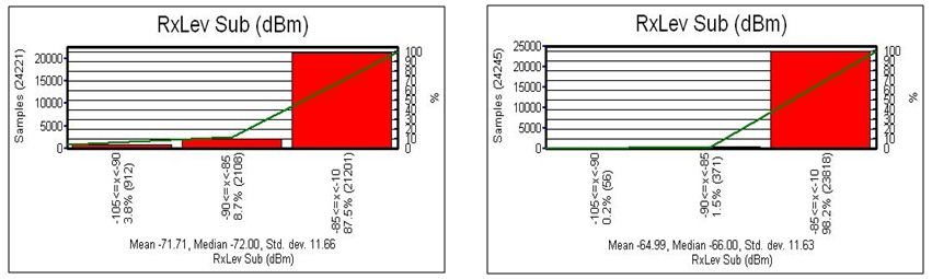 Bar chart 1a: RxLev statistic before swap Bar chart 1b: RxLev statistic after swapRxQual Sub before and after swap:
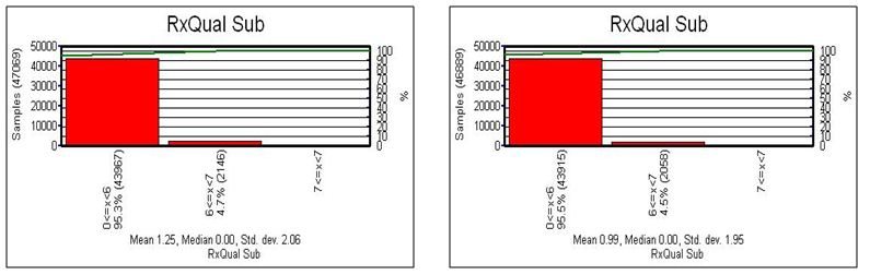 Bar chart 2a: RxQual Sub before swap Bar chart 2b: RxQual Sub After swap
Events and statistic before and after Swap: Preliminary Checklist before Functionality Test
- Collect Cellfile ; If not available create cell file
- Collect CDD file or Engineering Information Table
- Collect Neighbor information table
- Collect map of the target area with Drive Test route
- Collect Cluster Boundary Map
- Collect vector map and street information
- Contact list with the responsible RF engineers and the OMC/BSS engineers on BSC/NOC
- Ensure all DT tools and inverters are working properly
- Ensure there are enough fuels in the car
- Ensure that there is enough balance in SIM card before leaving
- Ensure that Car is in good condition
- Ensure that there are no alarm in the site
- Calibrate the tools properly & measure if it is same RxLevel for all MS
- Ensure all the drivers of laptop, mobiles & GPS are installed properly
- Ensure you have backup software of Win XP, Laptop drivers, GPS drivers, TEMS
- Ensure phone battery is fully charged
- Ensure Laptop is fully charged
- Ensure you have connected +ve & -ve terminal of the inverter properly with car battery; mark the cables if necessary
- Fill up the DT daily log sheet
- Start a test log file to ensure that measurement is working fine
- Check that you have saved the log files after finishing the measuring tour
- Keep all the tools & accessories into the tool bag organized. No sharp bandings of cables or cable ties/tapes are not allowed in the bag.
- Check that you have switched off all the MS at the end of work
Single Site Functionality Test The SSFT is performed with BTSs, Transcoders, BSCs and MSCs installed. The results of each measurement shall be confirmed by pass/fail or registered in the data sheet..The test comprises the following steps in order to perform the SSFT
- Execution of Mobile to/from MSC test number on each sector
- Execution of Mobile to Mobile calls.
- Execution of Originating and terminating SMS from each sector
- Verification of correct antenna orientation and correct BCCH on each sector
- Verification of BCCH footprints plots with adequate mobile Receive and C/I levels.
- Verification of frequency hopping, AMR FR, AMR HR
- Verification of Receive and Transmit powers
- Verification of Handover and Signal Quality – RxQual (Full & Sub values)
- Verification of the Packet data calls (Upload and Download) with GPRS/EDGE if applicable
- Verification of working of the inter vendor Handover with the neighboring sites, where ever applicable
Common Problems One of the most common faults with a new site build is swapped feeders. This occurs when the feeder(s) for one sector is connected to a different sector.DT engineer will ensure that there is no problem over the site regarding to sectors swap and bad quality. If DT engineer will find any issues or not sure about that, then he must inform the UCE DT coordinator or BSS engineer of Huawei.Common problems expected are—–1. Swapped feeders.2. Wrong tilts or wrong azimuths.3. Damaged hardware on the sites or other RBSs.4. Parameter errors, sites going down during the drive, or5. Wrong antenna types installed.Feeder Swap /Cross Feeder Test:Procedure
- Drive along the main beamwidth of the antenna (around 50 to 250 m)
a) First preference DT in locked channel per cellb) Second preference DT in idle mode per cell
- While driving along sector A, if cell reselected along B or C or call camped in opposite sector then there is a feeder swap between that two sectors. Similar cases for sector B or C.
- Also during drive along sector A, if cell A have poor RxLevel (-80 to –95 dBm within 50 m) while other sector (B or C) have good RxLevel (-47 to -60 dBm) then there is a possibility of cross feeder.
Feeder Swap /Cross Feeder Test The first step to identify swapped feeders is to display the strongest BCCH (by signalStrength) along the drive route as shown in figure s.Figure-1 : It is clearly evident that the feeders for Sector1 (BCCH 48) and Sector 3 (BCCH64) are swapped. Alternatively, it could be that the frequency allocations are wrong for those two sectors.Figure-2 : Suppose we run a drive test through the area served by the cell whose feeders are crossed display the ServBCCH attribute on the Map while the cell sectors are colored by BCCH. This is what we might see: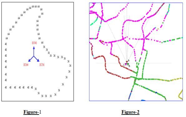 What is Crossed Feeder Issue?
- There are server types of crossed feeder:
- Crossed transmit feeders
- Crossed receive feeders
- Crossed transmit and receive feeders
Crossed transmit feeders:Crossed transmit feeders will result in the swap of 2 or more sectors BCCH frequency and TCH’s. As the sectors are pointing in the incorrect direction, performance will suffer as the frequency plan has been changed and a greater degree of interference will be present.In DT, we will find that the handset receives the single which shouldn’t have been received in the current cell.
Crossed receive feeders:It is not easy to detect this fault by DT, because the BCCH frequencies will appear exactly as they were designed. However, the statistics for the cell would help us to detect the fault:
- Uplink signal strength would be very poor
- Link balance would be larger than expected
- Handover success rate would be very low
Crossed transmit and receive feeder:The symptom is similar with the fault “crossed transmit feeder”, and we can detect the fault by DT easily .
The problems raised by crossed feeder issue:Crossed feeder will raise many problems, such as:
- A greater degree of interference
- A poor uplink signal strength
- A poor performance of handover
The problems raised by crossed feeder issue: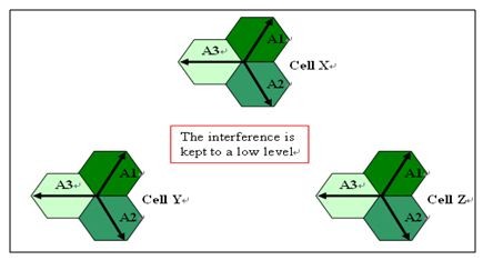 Normal Situation
 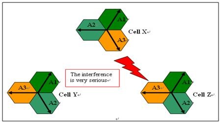 Crossed Feeder Situation.Log Issues
- Call
- SMS
- GPRS
- Handover
- Co-channel handover
Call:We take call sample for minimum one minute. it is very important in drive test because through call sample RNO engineer call analyses the present situation of their network quality. By this log the can understand if there is any drop call or silent call and any noise behind the call. They can take necessary steps if the need to improve their service.
SMS:Just we take the record because to see that the sms service is running successfully.
GPRS: Just we take the record because to see that the PDP context activated.
Handover:Handover is an important issue in Drive test or in the swap test. Basically after initialization of the new BTS it is important to observe the proper handover quality in that serving BTS for every cell. There are two types of handover performed during DT of a BTS. These are the Co channel Handover and the Neighbor channel Handover. The purpose of the handover is to see the quality of handover between the co and neighbor channel handover that how frequently the handover is made.Before ho takes place, system needs to decide the best candidate. First it repeats consecutive measurements to rank the cells according to HO algorithm. Please note that HO algorithm in different vendors systems or even in operators using the same equipment could be different. Some systems might rank the cells looking to their signal strength or some can rank them looking to their Path Loss or some can use both.
The purpose of handover analysis in DT is:
- Understand the wireless handover performance of network.
- Find out whether the handovers are healthy in this network.
- What is typical handover failure in this network?
- Find out whether neighbor audit work is needed in this network.
Co- channel handover:Co-channel handover is the way to handoff the call in other cell of the BTS from the one cell of the same BTS. It is perform to watch the frequent handover capacity of the same BTS.Say this is our BTS and the serving cell is A,B,C. for the co-channel handover we have to hand off the call in an a sequence. Like from A to B then B to C and C to A like the clockwise way. After that we have to maintain the sequence in a alternative way that means the anticlockwise way which means that from A to C, C to B, and then B to A. After this stapes the handover mechanism is performed. During DT in TEMS 8.0.4 we normally perform this operation by targeting the BCCH of the serving cell to handoff the call. Normally co- channel handover perform from the close position of the serving BTS.
Problem in co-channel Handover:
- If the position of MS is far away from the serving BTS then it is impossible to perform the handover. It is because of the cell direction. Near to the BTS it is quite easy to take handover frequently of the serving BTS.
- If there is feeder cable swap then it is very difficult to take reading of the co-handover mechanism
- Some theme the BTS have overlaid and the under laid sub cell. On that case the handover may happen but there is an extra massage “Handover Intracell” which is not good always.
Neighbor handover:Neighbor handover is another basic objective of the DT. It ensures the network quality and the Call drop situation in a network. It also dedicates the coverage gap and the situation of the network coverage.In DT one has to perform the neighbor handover for the every serving cell of the BTS. Normally the handover perform between the neighbor cells of the serving cell which power is greater than any other serving BTS. Normally the handover is performWithout locking the frequency when the MS is in traffic mode and watch out the frequent handover between the neighbor cell. But some time we have to lock the frequency and perform handover by targeting the neighbor frequency.
Problems with the neighbor handover:
- Handover problem due to vendor separation: It is some time observes that there is a handover failure because of the vendor mismatch. GrameenPhone just change their BTS from Ericsson to Huawei. As a result it is quite difficult to make handover operation between these two vendors. Because of some parameter related to their technologies. In this situation it is observe that the new BTS keep the call and do not perform the handover operation to any old BTS even when the power level (Rx level) is too poor.
- Neighbor Cell Missing: Some time it is observed that the handover operation perform between two neighbor cell which are far away, even there is another cell close to the serving BTS. This situation basically occurs during targeting one frequency from another and the poor signal level due to the building or other things. In this situation during the handover operation suddenly the cell is appear after the handover perform. On that time the “neighbor cell missing “massage just appears.
- Co- handover Problem: If the whole process start from very close to the BTS then there might be chance of Co handover in the same BTS.
- Handover Intra cell: The cell from which we handoff the call to the other cell of other BTS, if serve OL and UL sub cell then the handover intra cell situation might come. It also occurs when we go far from the BTS, mostly from the high traffic area to the low traffic area and the TCH conversion from full rate to the half rate traffic.
Conclusion
In conclusion I have to attest my supervisor Asif Mohammad Badruddoza of UCE Telecom Solution Pvt Ltd. I really appreciate the way I have been guided through this internship program with UCE, beginning from the opportunity to take the time I needed to refresh and expand my knowledge in several issues concerning Drive Test and RF Parameters, over a somehow protected period where I could discover and learn to value my new working environment, and finally earned the confidence to deal with assignments myself. It is through them that I did enjoy my work every day. Having a rare opportunity to use the knowledge and skills that I had acquired, I learned how to handle critical network faults and got the new ideas.Career-wise, the internship program undoubtedly will enrich my curriculum vitae (CV). Also, having gotten a chance to interact with most staff, I have had an insight on how to shape my career towards a humanitarian job in the near future.The internship program gave me a chance not only to work with UCE but also a chance to learn from the good experts. This would reflect much onto my experience. Working with different business organizations was a rare chance for me.