A forward converter is a sort of switching power supply circuit that converts a DC input voltage into a higher or lower DC output voltage. The forward converter is a DC/DC converter that uses a transformer to increase or reduce output voltage (depending on the transformer ratio) while also providing galvanic isolation for the load. It works on the transformer action principle and uses a switching element (often a transistor or a MOSFET) to control energy transfer between the circuit’s input and output sides. With numerous output windings, it is possible to give both higher and lower voltage outputs concurrently.
While it superficially resembles a flyback converter, it operates in a fundamentally different manner and is generally more efficient. While the converter switching element (transistor) is conducting, energy is stored in the magnetic field in the transformer air gap. When the switch is turned off, the stored magnetic field collapses, and the energy is transmitted to the flyback converter’s output as an electric current. The flyback converter consists of two inductors that share a common core and windings of opposing polarity.
Here are the key components and operation principles of a forward converter:
Components:
- Transformer: The heart of the forward converter, which transfers energy from the input to the output side.
- Switching Element: A transistor or MOSFET that controls the switching action to regulate the output voltage.
- Diode: Used for rectification and to prevent reverse current flow.
- Capacitor: For smoothing the output voltage.
- Inductor: Often used in the output stage to filter the output voltage.
- Control Circuit: Provides the necessary control signals to the switching element to regulate the output voltage.
Operation:
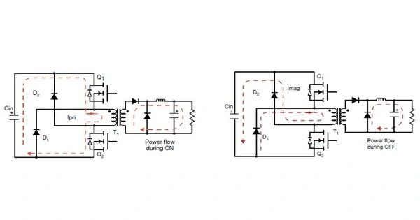
- Switch Closed (On-state): When the switching element is turned on, current flows through the primary winding of the transformer, storing energy in the transformer’s magnetic field.
- Switch Open (Off-state): The switching element is turned off, causing the magnetic field in the transformer to collapse. This change induces a voltage in the secondary winding of the transformer.
- Diode Conducting: The induced voltage drives current through the secondary winding and the diode, charging the output capacitor and supplying power to the load.
- Output Regulation: The control circuit monitors the output voltage and adjusts the duty cycle (on-time vs off-time) of the switching element to maintain the desired output voltage.
Advantages:
- Efficiency: Forward converters can achieve high efficiency due to their transformer-based design.
- Isolation: Provides electrical isolation between the input and output, enhancing safety and allowing for different ground potentials.
- Flexibility: Suitable for a wide range of input and output voltage levels.
Disadvantages:
- Complexity: Requires careful design and control circuitry.
- Electromagnetic Interference (EMI): May produce EMI due to switching action.
- Cost: Can be more expensive than simpler converter topologies like buck or boost converters.
Applications:
- Power Supplies: Used in various electronic devices, from consumer electronics to industrial applications.
- Battery Chargers: Efficiently charge batteries by converting one DC voltage to another.
- Renewable Energy Systems: Convert and manage power in solar and wind energy systems.
- Industrial Equipment: Powering motors, actuators, and other equipment in industrial settings.
Understanding the operation and design considerations of a forward converter is crucial for engineers and designers working on power electronics applications. Proper design and control are essential for achieving desired performance, efficiency, and reliability.