OVERVIEW OF THE REPORT
The overview of this project is to show how a fixed broadband wireless ISP gives internet connection from backbone to clients end. This project also consist of various wireless hardware description and connectivity from device to device and also how IP is managed for addressing, managing and securing from unauthorized access.
COMPANY OVERVIEW OF THE INTERNSHIP REPORT
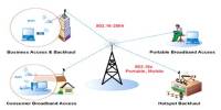
A wireless Internet service provider (WISP) is an Internet service provider (ISP) that allows subscribers to connect to a server at designated hot spots (access points) using a wireless connection such as Wi-Fi. This type of ISP offers broadband service and allows subscriber computers, called stations, to access the Internet and the Web from anywhere within the zone of coverage provided by the server antenna. This is usually a region with a radius of several kilometers. The simplest WISP is a basic service set (BSS) consisting of one server and numerous stations all linked to that server by wireless. More sophisticated WISP networks employ the extended service set (ESS) topology, consisting of two or more BSSs linked together at access points (APs). Both BSS and ESS are supported by the IEEE 802.11b specification. My company X-net started its business in 2007. My company X-Net Limited is a business unit of Genesis Technology Group. It provides nationwide high-speed data connectivity for the corporate and institutional clients. The prime objective of X-Net is to develop a nationwide secured data communication service network that is an integral part for the success of today’s business. X-Net Fiber Optic, Microwave & Radio link offers last mile connectivity to corporate and institutional clients in Bangladesh. The network provides a highly reliable and cost effective communications network for data applications to support the growing needs of financial, corporate, commercial markets.
OBJECTIVE OF THE REPORT
Objective of my project is to give an abstract view of BWA network connectivity between backbone connections to access layer connection.
This report’s aimed to provide the standard acceptance of a new Broadband Wireless Access (BWA), Base Station (BTS), BTS Backhaul/Backbone and some of the features of each network segment in BWA infrastructure and management.
ORGANIZATION OF THE PROJECT REPORT
In ISP sector different branches are situated in different locations. They often need to exchange correct and accurate information within them to provide efficient service to their customers. The objective of my project is to describe an infrastructure of data communication highway to develop a BWA network connectivity for WAN, especially for home or corporate houses, for faster data transmission among their different branches located in different locations.
The project is divided into 8 chapters. The first chapter is the introduction chapter. This chapter describes the overview of the report, company overview and objective of the report.
The chapter two is about various transmission media, like STP, UTP, Coaxial, Fiber optic, radio frequency, microwave, infrared. . Chapter tree is about layer and IP. Like different layer, IP addressing, Subnet mask, various TCP ports. In Chapter four described about Network connectivity device, like backhaul, Access Point, Access Point Cluster, Subscriber Module, switch and router. Chapter five is about setting up the wireless network connectivity and configures AP/SM to create a new connection. In Chapter six described about different servers and firewall. In chapter seven described about Network Monitoring, like MTU switches, monitoring connectivity devices, managing CRM, NetSys, AXSpro, and Cacti/MRTG. In chapter eight described about conclusion and Recommendation.
TRANSMISSION MEDIA
Various physical media can be used for the actual transmission. Each one has its own niche in terms of bandwidth, delay, cost and each of installation and maintenance.
When choosing the transmission media, consider the following:
- Transmission Rate
- Distances
- Cost and Ease of Installation
- Resistance to Environmental Conditions
Types of media:
- Physical media
- Wireless media
PHYSICAL MEDIA
First, consider the three common types of physical media that were introduced previously: twisted pair, coaxial cable, and fiber optic cable.
Twisted Pair
Twisted pair media consists of two insulated wires (usually copper) that are twisted around each other and covered with a plastic casing.
Twisted pair cable comes in two flavors:
- Shielded twisted pair (STP) includes a layer of shielding that protects the wires from electromagnetic interference.
- Unshielded twisted pair (UTP) is a lower cost solution that does not include protective shielding.
Shielding becomes more important as the speeds and distances increase across the LAN. The specifications for the number of twists per foot of cable also become very.
Critical at higher speeds. UTP transmission capacity is categorized by a quality grade rating that refers to twists per foot, conductor size, and electrical attributes:
- CAT1 and CAT2 are voice grade cables designed for analog and digital voice. Flat, untwisted CAT1 phone wire (sometimes called “silver satin“) is generally unsuitable for LANs even though it works well for voice. This is because voice requires much less bandwidth (less than 64 Kbps) than a typical LAN.
- CAT3, CAT4, and CAT5 are data grade cables that transmit at 16Mbps, 20 Mbps, and 100 Mbps respectively.
- Level 6 and Level 7 cables are enhanced versions of CAT5 cables for which standards are still emerging.
Table 2.1: Types of UTP & STP cable
Twisted Pair Connector
The twisted pair connector is called an RJ45 plug. The RJ45 resembles a phone plug (RJ11) except that the RJ45 has eight wires and eight pins (four pair of send/receive) as compared to the RJ11’s four wires and pins (two pair of send/receive).
Coaxial Cable
Coaxial cabling has a single copper conductor at its center. A plastic layer provides insulation between the center conductor and a braided metal shield. The metal shield helps to block any outside interference from fluorescent lights, motors, and other computers.
Although coaxial cabling is difficult to install, it is highly resistant to signal interference. In addition, it can support greater cable lengths between network devices than twisted pair cable. The two types of coaxial cabling are thick coaxial and thin coaxial. Thin coaxial cable is also referred to as thin net. 10Base2 refers to the specifications for thin coaxial cable carrying Ethernet signals. The 2 refer to the approximate maximum segment length being 200 meters. In actual fact the maximum segment length is 185 meters. Thin coaxial cable is popular in school networks, especially linear bus networks.
Thick coaxial cable is also referred to as thick net. 10Base5 refers to the specifications for thick coaxial cable carrying Ethernet signals. The 5 refer to the maximum segment length being 500 meters. Thick coaxial cable has an extra protective plastic cover that helps keep moisture away from the center conductor. This makes thick coaxial a great choice when running longer lengths in a linear bus network. One disadvantage of thick coaxial is that it does not bend easily and is difficult to install.
Fiber Optic Cable
Fiber optic cable is constructed of flexible glass or plastic and transmits information via photons or light. It comes in two forms:
- Thick fiber optic cable (62.5 microns) is for slower rates and shorter distances (up to 2 km). Thick fiber is typically used for multi-mode (MM) adapters, which transmit multiple frequencies simultaneously.
- Thin fiber optic cable (5 microns) is designed for faster rates and farther distances (up to 40 km). Thin fiber is typically used for single mode (SM) transmission (single frequency adapters).
There are many different fiber connector types, but the two most common are barrel or bayonet connectors called ST (“stick-and-turn”) and square push-in connectors called SC (“stick-and-click”). While industry standards are leaning towards SC as the connector of choice, increased attention is being given to emerging connector types, such as the MT-RJ (which looks like a fiber version of the RJ45 plug).
Table 2.2: Ethernet Cable Summary
Specification | Cable Type | Maximum length |
10BaseT | Unshielded Twisted Pair | 100 meters |
10Base2 | Thin Coaxial | 185 meters |
10Base5 | Thick Coaxial | 500 meters |
10BaseF | Fiber Optic | 2000 meters |
100BaseT | Unshielded Twisted Pair | 100 meters |
100BaseTX | Unshielded Twisted Pair | 220 meters |
Computers and peripherals can also comminute via infrared light. Infrared (IR) communications represents a major advance in portable PC technology, since it supports many mobile-computing activities. For example, two portable PC users can quickly exchange a file or other data without physically connecting their computers.
Microwave technology is used to interconnect LANs between buildings. This requires microwave dishes on both ends of the links. The dishes must be in line of sight to transmit and collect the microwave signals. Microwave is used to bypass the telephone company when connecting LANs between buildings. One major drawback of microwave technology is that the frequency band used requires licensing by the FCC. Once a license is granted for a particular location, that frequency band cannot be licensed to anyone else, for any purpose, within a 17.5-mile radius.
Table 2.3: Fiber Optic Vs Copper Wire
Table 2.4: Media Comparison Chart
MEDIA | ADVANTAGES | DISADVANTAGES |
Twisted Pair Cable | Inexpensive Well understood Easy to add nodes | Sensitive to noise Short distances Limited bandwidth Security – easily tapped |
Coaxial Cable | High bandwidth Long distances Noise immunity | Physic dimensions Security – easily tapped |
Optical Fiber Cable
| Very high bandwidth Noise immunity Long distances High security Small size | Connections T splitters |
WIRELESS MEDIA
First, consider the three common types of wireless media that were introduced previously: radio, microwave, and infrared.
Radio
It is a wireless transmission medium that is used to communicate information through radio signals in air, over long distance such as between cities and countries. In this medium, a transmitter is required to send messages (signals) and receiver is required to receive them. To receive the broadcast radio signal, the receiver has an antenna that is located in the range of signal. Some networks use a special device called transceiver used to send and to receive messages in the form of radio signals.
The frequencies falling between 3000 hertz (3 kHz) and 300,000,000,000 hertz (300 GHz) are called RADIO FREQUENCIES (abbreviated RF) since they are commonly used in radio communications. This part of the radio frequency spectrum is divided into bands, each band being 10 times higher in frequency than the one immediately below it. This arrangement serves as a convenient way to remember the range of each band. The RF bands are shown in table 2.5- The usable radio-frequency range is roughly 10 kilohertz to 100 gigahertz. [1]
Table 2.5: Radio frequency band
Microwave
Microwaves are radio waves that provide a high speed transmission. In Microwaves transmission, data is transmitted from one station to another. Microwave station contains an antenna, transceiver (transmitter & receiver) and other equipments that are required for microwave communication. Microwave uses the line-of-sight transmission, which means that in microwave transmission system the data signals travel in a straight path and cannot bend. Microwave stations or antennas are usually installed on the high towers or buildings. Thus microwave stations need to be placed within 20 to 30 miles of each other. Each microwave station receives signals from the previous stations. In this way, data is transmitted from one place to another. The data transmission speed of microwave transmission is up to 150 Mbps. Microwave transmission is used in environments where installing physical transmission media is impossible and where line-of-sight transmission is available. It is used in wide-open areas. Today, it is used by telephone companies, cable television providers, universities etc.
There are two types of microwaves:
Terrestrial – Used to link networks over long distances but the two microwave towers must have a line of sight between them. The frequency is usually 4-6GHz or 21-23GHz. Speed is often 1-10Mbps. The signal is normally encrypted for privacy. Two nodes may exist.
Satellite – A satellite orbits at 22,300 miles above the earth which is an altitude that will cause it to stay in a fixed position relative to the rotation of the earth. This is called a geosynchronous orbit. A station on the ground will send and receive signals from the satellite. The signal can have propagation delays between 0.5 to 5 seconds due to the distances involved. The transmission frequency is normally 11-14GHz with a transmission speed in the range of 1-10Mbps. [2]
Infrared
Infrared light is part of electromagnetic spectrum that is shorter than radio waves but longer than visible light. Its frequency range is between 300 GHz and 400 GHz that corresponds to wavelength from 1mm to 750 nm. Infrared has long been used in night vision equipment and TV remote control. Infrared is also one of the physical media in the original wireless LAN standard, that’s IEEE 802.11. Infrared use in communication and networking was defined by the IrDA (Infrared Data Association). Using IrDA specifications, infrared can be used in a wide range of applications, e.g. file transfer, synchronization, dial-up networking, and payment. However, IrDA is limited in range (up to about 1 meter). It also requires the communicating devices to be in LOS and within its 30-degree beam-cone. Light may interfere with the signal.
The types of inferred are:
Point to point – Transmission frequencies are 100GHz-1, 000THz. Transmission is between two points and is limited to line of sight range. It is difficult to eavesdrop on the transmission. The speed is 100Kbps to 16Mbps
Broadcast – The signal is dispersed so several units may receive the signal. The unit used to disperse the signal may be reflective material or a transmitter that amplifies and retransmits the signal. Normally the speed is limited to 1Mbps. The transmission frequency is normally 100GHz-1,000THz with transmission distance in 10’s of meters. Installation is easy and cost is relatively inexpensive for wireless.
LAYER AND IP
NETWORK LEYAR
The International Standards Organization (ISO) has specified a general architecture of network specifications in their DIS7498 model (applicable to most any digital network). Consisting of seven “layers,” this outline attempts to categorize all levels of abstraction necessary to communicate data.
- Level 1: Physical specifies electrical and mechanical details of communication: wire type, connector design, signal types and levels.
- Level 2: Data link Defines formats of messages, how data is to be addressed, and error detection/correction techniques.
- Level 3: Network Establishes procedures for encapsulation of data into “packets” for transmission and reception.
- Level 4: Transport Among other things, the transport layer defines how complete data files are to be handled over a network.
- Level 5: Session Organizes data transfer in terms of beginning and end of a specific transmission. Analogous to job control on a multitasking computer operating system.
- Level 6: Presentation Includes definitions for character set, terminal control, and graphics commands so that abstract data can be readily encoded and decoded between communicating devices.
- Level 7: Application The application layer contains a variety of protocols that are commonly needed. It gives file transfer, electronic mail, remote job entry, directory lookup and various other general purpose and special purpose facilities.
When a node “talks” on the network, it is generating a signal on the network wiring, be it high and low DC voltage levels, some kind of modulated AC carrier wave signal, or even pulses of light in a fiber. Nodes that “listen” are simply measuring that applied signal on the network (from the transmitting node) and passively monitoring it. If two or more nodes “talk” at the same time, however, their output signals may clash (imagine two logic gates trying to apply opposite signal voltages to a single line on a bus!), corrupting the transmitted data.
INTERNET PROTOCOL
The Internet is a computer network made up of thousands of networks worldwide. No one knows exactly how many computers are connected to the Internet. It is certain, however, that these number in the millions and are increasing at a rapid rate. All computers on the Internet communicate with one another using the Transmission Control Protocol/Internet Protocol suite, abbreviated to TCP/IP. Computers on the Internet use client/server architecture. This means that the remote server machine provides files and services to the user’s local client machine. Software can be installed on a client computer to take advantage of the latest access technology.
Internet protocols are sets of rules that allow for communication on the Internet. The following major protocols are accessible on the Web:
- E-mail (Simple Mail Transport Protocol or SMTP)
Distributes electronic messages and files to one or more electronic mailboxes
- Telnet (Telnet Protocol)
Facilitates login to a computer host to execute commands
- FTP (File Transfer Protocol)
Transfers text or binary files between an FTP server and client
- Usenet (Network News Transfer Protocol or NNTP)
Distributes Usenet news articles derived from topical discussions on newsgroups
- HTTP (Hyper Text Transfer Protocol)
Transmits hypertext over networks. This is the protocol of the WWW.
IP is a required TCP/IP standard defined in RFC 791, “Internet Protocol (IP).” IP is a connectionless, unreliable datagram protocol primarily responsible for addressing and routing packets between hosts.
Connectionless means that a session is not established before exchanging data. Unreliable means that delivery is not guaranteed. IP always makes a best-effort attempt to deliver a packet. An IP packet might be lost, delivered out of sequence, duplicated, or delayed. IP does not attempt to recover from these types of errors. The acknowledgment of packets delivered and the recovery of lost packets is the responsibility of a higher-layer protocol, such as TCP. An IP packet, also known as an IP datagram, consists of an IP header and an IP payload, as shown in the following illustration. The IP header contains the following fields for addressing and routing:
Table 3.1: IP header function
| IP header field | Function |
Source IP address | The IP address of the original source of the IP datagram. |
Destination IP address | The IP address of the final destination of the IP datagram. |
Time-to-Live (TTL) | Designates the number of network segments on which the datagram is allowed to travel before being discarded by a router. The TTL is set by the sending host and is used to prevent packets from endlessly circulating on an IP internetwork. When forwarding an IP packet, routers are required to decrease the TTL by at least 1 |
TCP ports
TCP ports use a specific program port for delivery of data sent by using Transmission Control Protocol (TCP). TCP ports are more complex and operate differently from UDP ports.
While a UDP port operates as a single message queue and the network endpoint for UDP-based communication, the final endpoint for all TCP communication is a unique connection. Each TCP connection is uniquely identified by dual endpoints.
Each single TCP server port is capable of offering shared access to multiple connections because all TCP connections are uniquely identified by two pairs of IP address and TCP ports (one address/port pairing for each connected host).
TCP programs use reserved or well-known port numbers, as shown in the following illustration.
The server side of each program that uses TCP ports listens for messages arriving on their well-known port number. All TCP server port numbers less than 1,024 (and some higher numbers) are reserved and registered by the Internet Assigned Numbers Authority (IANA).The following table is a partial list of some well-known TCP server ports used by standard TCP-based programs.
Table 3.2: Different TCP ports
TCP port number | Description |
20 | FTP server (data channel) |
21 | FTP server (control channel) |
23 | Telnet server |
53 | Domain Name System zone transfers |
80 | Web server (HTTP) |
139 | NetBIOS session service |
IP addressing
Each TCP/IP host is identified by a logical IP address. This address is unique for each host that communicates by using TCP/IP. Each 32-bit IP address identifies a location of a host system on the network in the same way that a street address identifies a house on a city street.
Just as a street address has a standard two-part format (a street name and a house number), each IP address is separated internally into two parts—a network ID and a host ID.
IP address classes
The Internet community has defined five address classes. Class A, B, and C addresses are used for assignment to TCP/IP nodes.
The class of address defines which bits are used for the network and host ID parts of each address. The address class also defines how many networks and hosts per network can be supported.
The following table uses w.x.y.z to designate the four octet values in any given IP address. The table is used to show:
Table 3.3: IP address classes
Class | Value of (w) | Network ID | Host ID | Number of networks | Number of hosts per network |
A | 1–126 | w | x.y.z | 126 | 16,777,214 |
B | 128–191 | w.x | y.z | 16,384 | 65,534 |
C | 192–223 | w.x.y | z | 2,097,152 | 254 |
D | 224–239 | Reserved for multicast addressing | N/A | N/A | N/A |
E | 240–254 | Reserved for experimental use | N/A | N/A | N/A |
Private Networks and Subnets
The governing bodies that administer the Internet Protocol have identified certain networks as reserved for internal use. In general, intranets that use these networks can reduce the difficulty in administering their IP configuration and Internet access. These three networks, along with their default subnet masks, are listed below.
Table 3.4: Private IP address and default mask
Network address | Default mask |
10.0.0.0 | 255.0.0.0 |
172.16.0.0 | 255.240.0.0 |
192.168.0.0 | 255.255.0.0 |
NETWORK CONNECTIVITY DEVICES
There are many different devices that can be used to configure a network. Besides choosing the Network Connectivity Devices you will use for your network, you need to decide which medium and topology you will use. At some point, traffic problems can arise along with broadcast storms that can be eliminated by implementing a simple solution.
There are a wide variety of network connectivity devices available for use on the wireless network.
- Backhaul Module (BH)
- Access Point (AP)
- Access Point Cluster
- Cluster Management Module (CMM)
- Subscriber Module (SM)
- Switches
- Router
Backhaul Module (BH)
The device that provides point-to-point connectivity link to an AP cluster through a selected AP.
Types of Backhaul:
I. Backhaul Timing Master
II. Backhaul Timing Slave
- I. Backhaul Timing Master: A module that is used in a point-to-point link, and controls the air protocol and configurations for the link.
- II. Backhaul Timing Slave: A module that is used in a point-to-point link, and accepts configuration and timing from the master module.
Master and slaves are not pre-configured (they are the same part number for ordering). During the installation process, the operator configures each particular backhaul as either a master or a slave.
Access Point (AP)
This is one module that distributes network or Internet services in a 60° sector to 200 subscribers or fewer.
How AP works:
Each SM communicates with an AP in an assigned time slot that the AP controls. The AP coordinates the needs of SMs for data in both the downlink and the uplink to provide seamless communication across the entire network. Each AP controls SM bandwidth management. All SMs registered to an AP receive and use the same bandwidth management information that is set in their Access Point. The Canopy software uses token buckets to manage the bandwidth of each SM. Each SM employs two buckets: one for uplink and one for downlink throughput. These buckets are continuously being filled with tokens at a rate set by the Sustained Data Rate variable field in the AP.
Properties of AP:
Frequency range: 2.4 to 2.4835 GHz, 5.25 to 5.35 GHz or 5.725 to 5.825 GHz
Encode method: TDD/TDMA
Maximum Bandith: 10 Mbps
Maximum Throughput:
Downlink: 4.6 Mbps at default allocation of 75%, but variable based on packet size.
Uplink: 1.6 Mbps at default allocation of 25%, but variable based on packet size.
Modulation Type: Frequency Shift Keying
Receiver Sensitivity: −83 dBm
Operational range:
Up to 2 miles (3.2 km) with integrated antenna in the 5.2-GHz band.
Up to 5 miles (8 km) with integrated antenna in the 2.4-GHz band
Up to 10 miles (16 km) with SM mounted to passive reflector in the 5.7-GHz band.
Up to 15 miles (24 km) with SM mounted to passive reflector on the SM in the 2.4-GHz band.
Transmitter Power: ~23 dBm
Signal spreading ability: 60° x 60° beam width.
Power required:
0.3 A @ 24 VDC (7.2 watts) typical.
Access Point Cluster:
Two to six APs that together distribute network or Internet services to a community of subscribers. With each AP covering a 60 degree sector, a cluster can cover as much as 360 degrees.
Cluster Management Module (CMM):
A module that provides power, PS timing, and networking connections for an AP cluster. If this CMM is connected to a BH (Backhaul Module), then this CMM is the central point of connectivity for the entire site. The CMM is a critical element in the operation of the Canopy system. At one AP cluster site or throughout an entire wireless system, the CMM provides a GPS timing pulse to each module, synchronizing the network transmission cycles.
Necessity:
All signaling device need timing synchronization. Without proper timing synchronization an AP is unsynchronized, and a BH timing master cannot synchronize a BH timing slave. An unsynchronized module may transmit during a receive cycle of other modules. This can cause one or more modules to receive an undesired signal that is strong enough to make the module insensitive to the desired signal.
Functionality:
The following way CMM provide proper timing:
Scenario 1:
A CMM provides sync in Ethernet protocol to a collocated AP.
This AP sends the sync in multipoint protocol over the air to SMs.
Scenario 2:
A CMM provides sync in Ethernet protocol to a collocated BH timing master.
This BH timing master sends the sync in point-to-point protocol over the air to a BH timing slave.
Scenario 3:
A CMM provides sync in Ethernet protocol to a collocated AP.
This AP sends the sync in multipoint protocol over the air to an SM.
This SM delivers the sync in Ethernet protocol to a collocated AP.
This AP passes the sync in multipoint protocol in the additional link over the air to SMs.
Scenario 4:
A CMM provides sync in Ethernet protocol to a collocated AP.
This AP sends the sync in multipoint protocol over the air to an SM.
This SM delivers the sync in Ethernet protocol to a collocated BH timing master.
This BH timing master passes the sync in point-to-point protocol in the additional link over the air to a BH timing slave.
Scenario 5:
A CMM provides sync in Ethernet protocol to a collocated BH timing master.
This BH timing master sends the sync in point-to-point protocol over the air to a BH timing slave.
This BH timing slave delivers the sync in Ethernet protocol to a collocated AP.
This AP passes the sync in multipoint protocol in the additional link over the air to SMs.
Ability and other factor:
Network Interconnection:
A CMM contains an 8-port managed switch which supports Power over Ethernet (PoE) on each port and connects up to 8 APs, BHMs, BHSs, or Ethernet feeds. A CMM auto-negotiates to match inputs that are either 100 BaseT or 10 BaseT, and either full duplex or half duplex. These parameters can also be set by the operator if so desired.
Power Distribution
A CMM distributes power to up to 8 APs, BHMs, or BHSs using Power over Ethernet (PoE). Ports can be powered or not powered, using a browser interface to the managed switch. Input to a CMM is nominal 24 V DC, and output to the modules is also nominal 24 V DC. The CMM comes with a separate 115/230 V AC to 24 V DC power converter.
Sync Distribution
A CMM micro distributes synchronization to Access Point modules (APs) and Backhaul
Timing Master Modules (BHMs). It receives timing information from Global Positioning System (GPS) satellites through an antenna, and distributes the synchronization signal to up to 8 modules (APs or BHMs). The 1 pulse-per-second timing received from the GPS is embedded in the 24 V power that is sent to each module.
Subscriber Module (SM)
A customer premises equipment (CPE) device that extends network or Internet services by communication with an AP or an AP cluster.
Properties of SM:
Frequency range: 2.4 to 2.4835 GHz, 5.25 to 5.35 GHz or 5.725 to 5.825 GHz
Encode method: TDD/TDMA
Maximum Bandwidth: 10 Mbps
Maximum Throughput:
Downlink: 4.6 Mbps at default allocation of 75%, but variable based on packet size.
Uplink: 1.6 Mbps at default allocation of 25%, but variable based on packet size.
Modulation Type: Frequency Shift Keying
Receiver Sensitivity: −83 dBm
Operational range:
Up to 2 miles (3.2 km) with integrated antenna in the 5.2-GHz band.
Up to 5 miles (8 km) with integrated antenna in the 2.4-GHz band
Up to 10 miles (16 km) with SM mounted to passive reflector in the 5.7-GHz band.
Up to 15 miles (24 km) with SM mounted to passive reflector on the SM in the 2.4-GHz band.
Transmitter Power: ~23 dBm
Signal spreading ability: 60° x 60° beam width.
Power required:
0.3 A @ 24 VDC (7.2 watts) typical.
0.35 A @ 24 VDC (8.4 watts) maximum (long cable runs, high ambient temperature, high transmit ratio). Set by downlink percentage.
Note: Access Point and Subscriber Module have similar specifications.
Connection and functionality:
All SMs registered to an AP receive and use the same bandwidth management information that is set in the AP where they are registered. The Canopy software uses token buckets to manage the bandwidth of each SM. Each SM employs two buckets: one for uplink and one for downlink throughput. These buckets are continuously being filled with tokens at a rate set by the Sustained Data Rate variable field in the AP. Canopy offers the Bandwidth and Authentication Manager (BAM) to manage bandwidth individually for each SM registered to an AP. BAM allows the setting of Sustained Uplink Data Rate, Sustained Downlink Data Rate, Uplink Burst Allocation, and Downlink Burst Allocation for the individual SM. Normal web browsing, e-mail, small file transfers, and short streaming video are rarely rate limited, depending on the bandwidth management settings in the AP or the BAM server. When the SM processes large downloads such as software upgrades and long streaming video, or a series of medium-size downloads, these transfer at a bandwidth higher than the Sustained Date Rate (unless no unused tokens remain in the bucket) until the burst limit is reached.
When the burst limit is reached, the data rate falls to the Sustained Data Rate setting. Then later, when the SM is either idle or transferring data at a rate slower than Sustained Data Rate, the burst limit recharges at the Sustained Data Rate. To support low-latency traffic such as VoIP (Voice over IP), the Canopy system implements a high priority channel. This channel does not affect the inherent latencies in the Canopy system but allows high-priority traffic to be immediately served. The high-priority pipe separates low-latency traffic from traffic that is latency tolerant, such as standard web traffic and file downloads. The Canopy system separates this traffic by recognizing the IPv4 Type of Service Low Latency bit (Bit 3). Bit 3 is set by a device outside the Canopy system. If this bit is set, the system sends the packet on the high-priority channel and services this channel before any normal traffic.
The SM setup must follow:
Vertically (the internal antenna is vertically polarized).
With hardware that the wind and ambient vibrations cannot flex or move.
Where a grounding system is available.
At a proper height:
– Higher than the tallest points of objects immediately around them (such as trees and buildings).
– at least 2 feet (0.6 m) below the tallest point on the roof or antenna mast (for lightning protection).
In a line-of-sight path:
– To the AP in the RF link.
– That will not be obstructed by trees as they grow or structures that are later built.
Note: Visual line of sight does not guarantee radio line of sight.
Switches
A switch is a small device that joins multiple computers together at a low-level network protocol layer. Technically, switches operate at layer two (Data Link Layer) of the OSI model.
Switches look nearly identical to hubs, but a switch generally contains more “intelligence” (and a slightly higher price tag) than a hub. Unlike hubs, switches are capable of inspecting the data packets as they are received, determining the source and destination device of that packet, and forwarding that packet appropriately. By delivering messages only to the connected device that it was intended for, switches conserve network bandwidth and offer generally better performance than hubs.
Like hubs, switches primarily are available for Ethernet, come in a range of port configurations starting with the four- and five-port models, and support 10 Mbps Ethernet, 100 Mbps Ethernet, or both.
As network speeds have increased, switches are measured against one another using the forwarding/filtering rate. This rate is simply an indicator of how fast data moves through a switch. LANs that use switches to join segments are called switched LANs or, in the case of Ethernet networks, switched Ethernet LANs.
Switches are cheaper than bridges due to their internal architecture. Bridges used general-purpose processors and RAM, whereas switches rely on custom integrated circuits.
Marconi’s ASX-4000 is an example of an ATM switch and the Marconi ESX-3000 is an example of an Ethernet switch.
There are four different approaches:
- A cut-through switch actually begins sending before the entire packet is received. As soon as the Destination Address is read, the switch makes a forwarding decision. The obvious advantage is speed, while the disadvantage is the potential for forwarding damaged packets that are not discovered until reading the Cyclical Redundancy Check (CRC) at the end of the packet.
- To avoid this possibility, store-and-forward switches read the entire packet, including the CRC, before forwarding. Store-and-forward increases the delay, or latency, through the device.
- Most damaged packets are the result of collisions, and can typically be identified within the first 64 bytes of the packet. So one compromise between the cut-through and store-and-forward methods is a fragment-free switch that waits until the first 64 bytes have arrived before making a decision. Packets that are less than 64 bytes, called runts, are considered invalid and discarded.
A hybrid switch starts off in cut-though mode that monitors the CRC errors in a packet flow. If the errors exceed a certain threshold, the switch resorts to the store-and-forward mode until the error rate decreases, at which point it resorts to cut-through again.
Router
Routers can interconnect networks over longer distances and over certain different media. Because routers support hierarchical network structures, they offer protection from network errors as well as electrical and data-related problems.
In a heterogeneous environment, such as networks, a need of connection devices which would inter-connect two different technologies is essential. In this environment the router is that device. As its name implies, the router also serves as a routing switchboard. Routers connect two or more networks and forward data packets between them. When data arrives from one of the segments, the router decides, according to its routing table, to which segment to forward that data. Even though each of the routers’ connections is to one physical network, that one network could connect to other networks through the use of other routers. This way, many networks can interconnect.
In the above configuration, router B’s table would say, for instance, that data going to network 4 should go to router C. Packets going from network 1 to network 4 would go through router B into network 2 and so on, till they reach their destination.
We would like to emphasize that router “know” only about networks, and not about hosts. In IP networks, routers utilize the fact that each host’s IP address contains two parts: the host’s network address, and the host’s number on that network. Routers examine the data destination address, extract, from it, the target network address, and decide, based on this network address, where to transfer the data.
A router is actually a special computer, which is dedicated to the task of interconnecting networks. It moves information from its source to its destination regardless of the middleware.
A router resembles a bridge (they both have conventional processor, memory and few different I/O interfaces, each for another network it connects), but while bridging occurs at the link layer, routing occurs at the network layer. This difference provides information to the router that the bridge doesn’t have access to.
Router responsibilities
Routers have two major responsibilities
- Optimizing the routing paths. A router uses a routing algorithm to determine the optimal path to the destination. These algorithms maintain routing tables, which contain route information such as destination/next, hop association. Routing algorithms has several goals:
- Optimality – finding the “best” route depending on the metric weightings used by the specific router (there are several metrics used by routers, each assigns different weights to routing algorithm’s parameters such as number of hops, delay)
- Simplicity and low overhead – router algorithms must be as efficient as possible with minimum utilization overhead. An efficient algorithm is particularly important when using routing software on a limited resources computer.
- Robustness and stability – routers are located at network junction points, therefore they must be robust with the ability to handle unusual behavior of hardware and software components.
- Rapid convergence – routers must agree on the optimal paths over the net in order to avoid loops. When a network event (computer/router failure, network segment going down etc.) force changes in the router’s routing tables, each router must perform recalculations based on the update messages it received from other routers on the net.
- Flexibility – is the ability to adapt accurately and quickly to network changes and events. For example when the optimal routes are no longer accessible or even optimal, due to some change in the network (segments going down, change in bandwidth, router queue size, network delay, and other variables), the routing algorithms should quickly adjust to the new situation and choose the next best route to replace the old ones which are not accessible any more.
2. Switching – transport of packets over networks. When computer wants to send a packet over the net, it formats a packet with the router’s physical address and the destination address (protocol address) of the target host. The router searches it’s routing tables for the destination host. If there is no entry for the destination host the router usually drops the packet, otherwise (there is an entry for the destination host) it replaces the physical address with the next hop’s address and retransmits the packet. The next hop isn’t necessarily the ultimate destination host; it may be another router that performs the same routine again. A packet may “visit” few routers /hosts on its route, each time its destination physical address changes.
Type of Routers
There are two types of routers:
1) Hardware routers
2) Software routers
Cisco is very popular brand in the market has got series of wide range of router products. Cisco has a number of different routers; amongst them are the popular 1600 series, 2500 series and 2600 series. The ranges start from the 600 series and go up to the 12000 series
Below are a few of the routers mentioned:
All the above equipment runs special software called the Cisco Internetwork Operating System or IOS.
Router characteristics
- A Cisco router is similar to a PC.
- Just like a PC, it has a CPU, RAM, ROM, and an operating system. Cisco’s operating system is IOS – Internetworking Operating System
- Cisco router stores its configuration files in NVRAM and its operating system in Flash. Flash can be either EEPROM chip or PCMCI card
- NVRAM and Flash are the types of RAM that retains the data even after the power is turned off
- The router does not need a very powerful CPU, and most routers run on 20 or
Router components
The basic components of any Cisco router are:
1) Interfaces
2) The Processor (CPU)
3) Internetwork Operating System (IOS)
4) RXBoot Image
5) RAM
6) NVRAM (Non-Volatile RAM)
7) ROM
8) Flash memory
Routers functionality
Routers are specialized computers that send messages (called data packets) to their destinations along thousands of pathways.
When sending a message/ data packets from one computer to another is done by routers, because they’re the crucial devices that let messages flow between networks, rather than within networks.
SETTING UP THE NETWORK CONNECTIVITY
NETWORK CONNECTIVITY
The backhaul links connects each base station in ring topology. The main node or aggregation point of the backhaul is situated in the Edge Station where the router aggregator is installed. Rapid Spanning Tree Protocol (RSTP) is implemented on the ring network to provide automatic fail over in case of link failure.
In this network needs to set three type nodes:
- Base Station (BTS)
- Multi-Tenant Unit (MTU) Collocated
- Multi-Tenant Unit (MTU) Wireless
Base Station (BTS) Setup:
A BTS contain the following devices:
1) Housing
2) Tower
3) Antenna
4) Radio signal
5) Cluster management module
6) Surge suppressor
7) Access controller
1) Housing:
It is basically a room on a roof top or in separate house where all important hardware and cables are kept protect from sun, rain and any other natural phenomena. It also provides security from unauthorized hardware intruder.
2) Tower:
Tower basically consist three or four leg rod which are almost basically 35 or 40 meter long.Tower holds the antenna which is most important parts of BTS. The property of tower decides how signal can be broadcast and what distance the signal can be broadcast.
3) Antenna:
Antenna is basically used for broadcast and receiving internet signal. It can multiplex several frequencies. The institutes where I work basically use 6 frequencies. For confidentiality it works around 5.1 GHz to 5.7 GHz. Each antenna can cover 60 degree area. As a result in one BTS each six antenna can cover 360 degree angel. It also has a radiation distance of about 1.6km.each antenna is connected to the pool by 30 degree angel vertically.
4) Radio signal:
There are two types of signal. One is LOS (line of sight) signal and another is Non LOS signal. For Non los signaling system the environment obstacle is not big issue. For example we use mobile phone which uses non LOS system for which we can use mobile both inside home and outside home. But in LOS system there must not any obstacle between access point antenna and user end antenna .In X-net there used LOS system.
5) Cluster management module:
Cluster management module consist of RF signal amplifier, modulation and demodulation .In this module signal is amplified and mixed with very high transmitting frequency and send to antenna and the antenna broadcast the signal. At receiving the signal passes through rectifier and demodulation module to get the original data frequency.
6) Surge suppressor:
Surge suppressor is special type of device which protect computer and other connected device from being damaged caused by electric strike during rainy season. It is directly grounded. Surge suppressor is connected between antenna and end device.
7) Access controller:
Access controller is a special mechanism which contains both hardware and software. It controls all traffic that comes in or out through ISP. The Latitude AXS Pro System is used in this control mechanism. The Latitude AXS Pro System is a total BWA solution with inherent QoS and complete flexibility on any access technology. It follows a robust and reliable architecture that provides scalability, high performance, interoperability, high level of security, and a cost-efficient operation in an all-IP environment.
Two or more BTS are connected to each other by following connectivity
- I. Point-to-point connectivity.
- II. Point-to-multipoint connectivity
I. Point to point backhaul setup:
- Locate all the nearest access point or subscriber module or any other backhaul unit.
- Find the height each of the backhaul because for point to point backhaul the two connecting backhaul unit must be the same height otherwise the frequency band will be lost due to over height or over lower height.
- Distance must not too far or too near. Otherwise signal strength will be reduced according t o radiation law.
- Line of sight must be clear i.e there must not any type of obstacle like building even if trees.
- There must not present any type high signal like television broadcast or any other type of radar frequency that interfere with canopy’s communicating signal.
- Both backhaul modules must adjust with same frequency range otherwise they cannot communicate each other.
- Both backhaul configured one as a master and another is a slave so that they can synchronize each other properly.
- After done the above procedure we have to tune the two unit according the signal strength, power level , noise level .
- Then we have to start testing by passing data for stability.
- If we see three or four hour that data loss is around 5% or less then the connection is stable.
If not then we have to retune the two backhaul by changing position or changing frequency range or changing necessary criteria such as height or reducing the distance between two backhaul.
If all the procedure is done correctly then backhaul connection is successfully established.
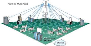
II. PTMP Network:
There may be two type of setup for point to multi point backhaul.
1. Using a single Access Point.
2. Using Access Point cluster.
For a single access point:
- The access point must have very high bandwidth, very high link capacity, very high signal broad casting range.
- It must have wide angular area generally 60 degree sector range.
- Distance must not too far or too near. Otherwise signal strength will be reduced according to radiation law.
- Line of sight must be clear i.e. there must not any type of obstacle like building even if trees.
- There must not present any type high signal like television broadcast or any other type of radar frequency that interfere with canopy’s communicating signal.
- All backhaul modules must adjust with same frequency range otherwise they cannot communicate each other.
- The access point is configured as a master and all other is a slave so that they can synchronize each other properly.
- After done the above procedure we have to tune the two unit according the signal strength, power level, noise level.
- Then we have to start testing by passing data for stability.
- If we see three or four hour that data loss is around 5% or less then the connection is stable.
If not then we have to retune the two backhaul by changing position or changing frequency range or changing necessary criteria such as height or reducing the distance between two backhaul.
If all the procedure is done correctly then backhaul connection is successfully established.
For Access Point cluster:
- Each access point is configured properly for sharing loads.
- Each access point sector is defined according to the needed.
- There must have proper mechanism to transfer load from one access point to another access point.
- Distance must not too far or too near. Otherwise signal strength will be reduced according t o radiation law.
- Line of sight must be clear i.e. there must not any type of obstacle like building even if trees.
- There must not present any type high signal like television broadcast or any other type of radar frequency that interfere with canopy’s communicating signal.
- All backhaul modules must adjust with same frequency range otherwise they cannot communicate each other.
- The access point is configured as a master and all other is a slave so that they can synchronize each other properly.
- After done the above procedure we have to tune the two units according the signal strength, power level, noise level.
- Then we have to start testing by passing data for stability.
- If we see three or four hour that data loss is around 5% or less then the connection is stable.
If not then we have to retune the two backhaul by changing position or changing frequency range or changing necessary criteria such as height or reducing the distance between two backhaul.
If all the procedure is done correctly then backhaul connection is successfully established.
MTU Wireless setup:
To setup MTU wireless-
1. Need a wireless antenna which is needed for establishing wireless communication between canopy wireless module and canopy access point.
I. The wireless antenna must configure with proper IP address for device to device communicating and also for remote management.
II. It is also configured with companies registered frequency band for signal transmitting.
III. To provide security it is also configured with user id and password.
IV. To provide power it is connected with special type power adopted called PoE.
2. To protect hardwires from bolt of the sky the cable comes from antenna connect directly to the surge protector device. This device is direct connected to the earthling and the data cable is directly connected to the MTU switch.
3. To prevent any type of intrusion all switch and other equipment is kept in a special type of cabinet called DC box or in other word data cabinet box .It contain multi plug, UPS for incase of loadshading or power failure and the MTU switch. The box always locked and the key is kept with proper authority.
4. The switch is a layer-3 switch .Now why layer three switch instead of layer two switch. Because layer-2 switch cannot be managed remotely. As named layer 3 it is managed by IP address. For intrusion prevention the switch is authenticate with user id and password. The switch is accessed remotely whenever a customer reported any type of problem issue who is connected to that switch. And necessary steps are taken.
5. Finally the device to device communicating from wireless antenna to end user device like router, server and PC there needs wires and connectors. The connector is type of RJ45 and cable used generally CAT5+. Generally from switch to antenna there is STP cables and from switch to end device UTP cable is used. As used CAT5+ cable is used for device to device connection cable length should not exceed 100 meter. But if exceed we must use signal booster device like repeater. The cable should be placed carefully so that water should not enter and the cable should not be disconnected.
MTU Collocated setup:
To setup MTU collocated we need two switch one is called BTS switch and other is called MTU switch. Now following procedure will be followed to setup collocation:
The BTS switch is directly connected to the base station controller. It is a layer 3 manageable switch. This switch is used for special management such that if the BTS down then find out the problem. Also monitoring how much bandwidth is used between switch and BTS. Through these switch all other router, switch and server is connected. Router is connected for dividing network and to add any other securities. The BTS switch is never connected to directly any customer device as mention previously it is only for managing BTS controller and Server.
Diagram of MTU collocated setup:
The second switch is called MTU switch. MTU switch is used to give connection to the customer.
It is used only for give connection and troubleshoots connection of the customer. The switch can be a layer two or layer three switches. Layer 2 switch is used when connection is used for official purpose. Layer 3 switch is used for customer cases.
For provide power failure protection all devices is connected IPS and UPS cluster i.e. two or more IPS, UPS and Batteries.
For connection from base switch to MTU switch STP cable is used to protect switch to switch high latency problem. From MTU switch to other end device UTP cable is used.
CPE Configuration:
There are 2 steps for CPE setup:
1. PC Setup,
2. Accessing the AP/SM/BH,
1. PC Setup:
a) IP Address
In order to access the Canopy module via its default IP address (169.254.1.1), your computer must be configured with an IP address on the same network (169.254.0.0):
I. If the computer is not configured for DHCP, then it must have a static IP address on the 169.254.0.0 network (i.e. 169.254.1.5).
II. If the computer is configured for DHCP, then it will automatically obtain an IP address on the 169.254 network shortly after you connect the Canopy module to the computer (as long as the computer is not connected to another module).
b) Web Browser
In order to ensure connectivity with the Canopy website’s web server, it is recommended that any proxy settings be disabled:
For IE: Internet Options > Connections > LAN Settings > Proxy Server (un-check the box).
2. Accessing the AP/SM/BH:
- Connect one end of a CAT-5 cable into the RJ-45 port of the Canopy module.
- Connect the other end of the CAT-5 cable into the female port of the power supply module.
- Connect the pig-tail connector of the power supply into the Ethernet port of your computer (female RJ-45).
- Connect the power supply to the power outlet, first ensuring that the power supply is compatible with local power levels (i.e. 110V-220V).
CPE (Subscriber Module) Configuration:
a) Home Page: Change the IP of PC/Laptop in the form of 169.254.1.xx (2-255)
On the Address Bar, enter the Default IP 169.254.1.1
b) AP Evaluation: Is a helpful tool in getting all the AP that the SM is sensing.
Go to Tools and then AP Evaluation to select the AP which has better power level. Here it is -61 and color code is 49.
C) Link capacity Test: Go to Tools and then Link capacity Test. Click on Start Test to check the link thoroughly.
Here Downlink Efficiency is 96 % and Uplink is 100%
d) SM Configuration: Click the “Configuration” and then “Radio”. Put the Color Code and Select all the frequencies that we are using for a particular sector of AP. Click “Save Changes” and then “Reboot”.
- IP Address Setup: In order to change the IP just click on “Configuration” and then IP.
Change the default IP Address (converted IP from MAC address of SM) Subnet mask and gateway. Click “Save Changes”.
- Trap Address setup: Go to “Configuration” and then “SNMP” .Write the Trap Address 172.30.0.139 in “Trap Address 1” option.
e) Clients address: Write the Details Address of Client in the “Site Information” to identify the customer more easily from remote login. Finally Click Save Changes .It will ask for Reboot. Click Reboot option for the SM to reboot. Reboot is must to save the Information that we put.
f) Finally SM should display a Session Status of “REGISTERED” in the Home page. We can also check the Power level, Jitter, Air Delay, Site information and so on from the Home page.
The following parameter (minimum value) should meet:
RSL>=-75
RSSI>=300
Jitter<=8
Downlink Efficiency>=80%
Uplink Efficiency>=80%
After completing these steps the network is being proper connected.
SARVER AND FIREWALL
SERVER
A server is a software program, or the computer on which that program runs, that provides a specific kind of service to client software running on the same computer or other computers on a network.
There are following server are using in X-Net Ltd.
- 1. DNS server
- 2. Mail Server
- 3. Web Server
- 4. FTP server
DNS Server
A DNS server is any computer registered to join the Domain Name System. A DNS server runs special-purpose networking software, features a public IP address, and contains a database of network names and addresses for other Internet hosts.
► DNS Root Servers
DNS servers communicate with each other using private network protocols. All DNS servers are organized in a hierarchy. At the top level of the hierarchy, so-called root servers store the complete database of Internet domain names and their corresponding IP addresses. The Internet employs 13 root servers that have become somewhat famous for their special role. Maintained by various independent agencies, the servers are aptly named A, B, C and so on up to M. Ten of these servers reside in the United States, one in Japan, one in London, UK and one in Stockholm, Sweden.
►DNS Servers and Home Networking
Computers on your home network locate a DNS server through the Internet connection setup properties. Providers give their customers the public IP address (es) of primary and backup DNS servers. You can find the current IP addresses of your DNS server configuration via several methods:
- on the configuration screens of a home network router
- on the TCP/IP connection properties screens in Windows Control Panel (if configured via that method)
- from ipconfig or similar command line utility
Mail Server
A mail server (also known as a mail transfer agent or MTA, a mail transport agent, a mail router or an Internet mailer) is an application that receives incoming e-mail from local users (people within the same domain) and remote senders and forwards outgoing e-mail for delivery. A computer dedicated to running such applications is also called a mail server. Microsoft Exchange, qmail, Exim and send mail are among the more common mail server programs.
●Permanent Storage
●User Defined Rules
●Mail Server Users List
●Communications Modules
Permanent Storage is where incoming mail is stored for later distribution to local users. Messages that are in transit to other destinations are also temporarily stored here. The typical structure of the storage area is that of a simple database.
User Defined Rules determine how the Mail Server deals with directing incoming messages to their destinations and also how it reacts to the sender of the message. Rules can be used to bar some senders from delivering mail to local users or to limit the types of messages local users can send and to whether they can send messages outside of the local network.
The Mail Server Users List is a database storing the names of local users that it will recognize and deliver incoming mail to.
The Communications Modules are the components that handle the transfer of incoming and outgoing messages to and from local users and other mail servers. The complexity and number of modules is dictated by the needs of the email system. A detailed discussion of communication modules will follow later.
The system administrator for an email system is often referred to as the “Postmaster.” The Postmaster is responsible for maintaining the list of users associated with the system and also establishes the Rules.
The operation of most Mail Servers is automatic. The Mail Server waits to receive local messages or messages from other mail servers and then processes/delivers them according to the established Rules.
►X-Net mail server:
Web server
A web server can be referred to as either the hardware (the computer) or the software (the computer application) that helps to deliver content that can be accessed through the internet. A web server is referred to as the software computer application that is installed in the hardware computer. A web server is what makes it possible to be able to access content like web pages, or other data from anywhere as long as it is connected to the internet. The hardware part is what houses the content, while the software part is what makes the content accessible through the internet.
It includes the hardware, operating system, Web server software, TCP/IP protocols and site content (Web pages and other files). If the Web server is used internally and not by the public, it may be called an “intranet server.”
The most common use of web servers is to host websites but there are other uses like data storage or for running enterprise applications. There are also different ways to request content from a web server. The most common request is the Hypertext Transfer Protocol (HTTP), but there are also other requests like the Internet Message Access Protocol (IMAP) or the File Transfer Protocol (FTP).
FTP Server
File Transfer Protocol (FTP) is a standard network protocol used to exchange and manipulate files over a TCP/IP-based network, such as the Internet. FTP is built on a client-server architecture and utilizes separate control and data connections between the client and server applications
File Transport Protocol (FTP) is a technology used to transfer files from a computer to a server. It’s often used on Internet websites for customers to upload or download files. It can also be used within private networks for a quick way to store and set permissions on file archives. FTP is not a secure technology, meaning passwords are passed in plain text and aren’t encrypted. FTP should only be used for simple downloading and uploading of files.
Upon connection, users can upload files to the server or download files to their local computers. Files are transferred in ASCII (text files) or Binary (images, programs, video and audio) format. Transfer occurs when a user’s FTP client issues commands to the FTP server. Commands include LIST (displays the files in a directory), STOR (initiates a command to upload a file to the server), RETR (retrieves or downloads a file from the server) and many others. When the user is finished and disconnects, the server makes that connection slot available for another user.
► X-Net FTP server:
Firewall
A Firewall is a set of related programs, located at a network gateway server that protects the resources of a private network from users from other networks. Basically, a firewall, working closely with a router program, filters all network packets to determine whether to forward them toward their destination. A firewall is often installed away from the rest of the network so that no incoming request can get directly at private network resources. There is a number of firewall screening methods. A simple one is to screen requests to make sure they come from acceptable (previously identified) domain names and IP addresses. For mobile users, firewalls allow remote access in to the private network by the use of secure logon procedures and authentication certificates.
Firewall is an electronic blocking mechanism that will not allow unauthorized intruders into a computer system. It is a kind of software program that blocks potential hackers from your individual computer or your computer network. Many different computer firewall software packages are available with a broad variety of costs and update options. Any computer that is always connected to the internet needs a firewall package.
Working Method of Firewall
If we have been using the Internet for any length of time, and especially if we work at a larger company and browse the Web while we are at work, we have probably heard the term firewall used. For example, we often hear people in companies say things like, “we can’t use that site because they won’t let it through the firewall.”
If we have a fast Internet connection into our home, we may have found ourself hearing about firewalls for our home network as well. It turns out that a small home network has many of the same security issues that a large corporate network does. We can use a firewall to protect our home network and family from offensive Web sites and potential hackers.
Basically, a firewall is a barrier to keep destructive forces away from your property. In fact, that’s why it’s called a firewall. Its job is similar to a physical firewall that keeps a fire from spreading from one area to the next. As you read through this article, you will learn more about firewalls, how they work and what kinds of threats they can protect you from.
Firewalls use one or more of three methods to control traffic flowing in and out of the network:
- Packet filtering – Packets (small chunks of data) are analyzed against a set of filters. Packets that make it through the filters are sent to the requesting system and all others are discarded.
- Proxy service – Information from the Internet is retrieved by the firewall and then sent to the requesting system and vice versa.
- Stateful inspection – A newer method that doesn’t examine the contents of each packet but instead compares certain key parts of the packet to a database of trusted information. Information traveling from inside the firewall to the outside is monitored for specific defining characteristics, and then incoming information is compared to these characteristics. If the comparison yields a reasonable match, the information is allowed through. Otherwise it is discarded.
Firewall Options
- Commercial Firewall Devices (Watch guard, Cisco PIX)
- Routers (ACL Lists)
- Linux
- Software Packages (Zone Alarm, Black Ice)
There are mainly three types of operations:
- Accept – accept the packet
- Drop – discard the packet silently
- Reject – actively reply the source that the packet is rejected.
NETWORK MONITORING
Responsibilities
- Monitoring MTU Switches
- Monitoring Connectivity of SM to AP
- Operating BOSS (Business & Operating Support Systems)
- Monitoring overall Network Traffic
MTU switches monitoring
X-Net have sevarel number of MTU under each base stasion (BTS). Its one my responsibilites to monitor and maintain these wsitch. Each swich has unique IP.
► Montitoring seswitch port to check the clients connectivity
► Monitoring switch port
► Configureing switch port
►Error controll
► Collecting MAC information to solve and detect client’s problem.
►Bandwidth controlling
Monitoring Connectivity of SM to AP:
►Each AP has unique IP. To check the connectivity using IP address.
►AP login page
► Clients in session status
► If the connectivity of AP to SM okay, then this SM home page will come.
Operating BOSS (Business & Operating Support Systems)
i. CRM (Customer Relationship Management)
ii. NetSys (Network Provisioning System)
iii. AXS Manager Tools
i. CRM (Customer Relationship Management):
CRM is the Customer Relationship Management System.It will be specifically designed for the complete management of various subscriber-related concerns. Its web-based management system will allow front-liners to access customer records. It has to a trouble ticketing system that captures and resolves customer feedback/concerns.
Function of CRM:
- Searching user’s account information using different parameters (Account No/Account Name/Customer name/Contact No etc.)
- Displaying account information, service information and activation history of a searched account
- Effectively manage the problem reporting and the resolution process
● Tracking every customers’ request/complaint/providing solution for assistance.
●Maintain a record of all services done on specific case
- Serving as a tool in troubleshooting, monitoring and retrieving wireless link information.
- Providing necessary tools for troubleshooting
ii. NetSys (Network Provisioning System):
NetSys will be the Network Provisioning System. It will be specifically designed for the complete management of various subscriber-related concerns. Its web-based management system will allow front-liners to access customer records regarding bandwidth utilization.
Function of NetSys:
- Acknowledgement of alerts, submit network advisory and view alerts history for downtime tracking.
- Alarming report in cases of network element failure or network abnormalities
- Providing an online monitoring tool for network elements such as SU (Subscriber Unit), AP (Access Point), BTS (Base station) and EGRESS.
- Proving a daily, weekly, monthly and yearly graphical representation of the bandwidth utilization of the different network elements.
- Providing summary reports on the traffic and latency of AP, BTS, EGRESS and SU.
iii. AXS Manager Tools:
AXS Manager Tools is a web-based system used for the administration of the AXS Manager. It provides a tool for portal customization, AXS Controller/ Base Station maintenance, account, server and user management and Access KEY generation.
Function of AXS manager:
- Enabling users to configure the IP and hostname of the AXS Manager Server
- Enabling the customization of the portal template and its banner
- Allowing users to specify walled garden sites
- Enabling users to add, edit and delete access controller and its sectors
- Setting the signal parameters’ threshold of a specific antenna
- Allowing users to set firewall rules on one or more access controllers
- Creation, extension, reactivation and expiration a subscriber’s account
- Generating and monitoring Access KEYs
- Creating and managing users for all systems
- Creating different packages with different bandwidth speed
- Managing the AXS Manager Server
- Providing users with troubleshooting tools and errors knowledge base
- Enabling users to add, edit and delete access controller and its sectors
Monitoring Overall Net Work Traffic
CACTY:
Cacti or MRTG is proposed for creation the utilization graph for corporate/big client. For every client separate username and password will be provide and by using that username and password client will be able to see/monitor their internal bandwidth utilization.
►Cacti Utilization graph
MRTG:
Its use for monitor AP to MTU switch’s Utilization Graph.
CONCLUSION
In this report I have presented an over view of the content of wireless network connectivity and discuss in brief about wireless devices what I have learned during my internship period. I have started with the basic idea about the BWA network overview of X-Net and Technology Overview. Then describe and analyze of different transmission and communication media. Transmission media are used for high speed data transition for ISP. I have described the regarding BWA Network stand and IP addressing mechanism. Then I described and configure SM/AP, adding interface, setting up wireless network connectivity, different kinds of server and include the end of my discussion including firewall mechanism.
Communication is a vital part for centralized data based and internet operations; where workstation located at different places log on to communicate with the central server or AP. Now days many ISP has adopted such type of centralized server based operation to meet the demand of the market in home or abroad.
RECOMMENDATION
To provide maximum service to the client I think X-Net need highest base station to avoid LOS issue. X-Net has some billing problem and X-Net has no billing server as well. Radius manager is a kind of billing server that provides a lot of features.
■ Prepaid billing
■ postpaid billing
■ Monthly billing
■ Traffic accounting (download, upload, total)
■ Creating invoices
■ Tracking of payments
■ Creating financial reports
■ Internet Access using prepaid card system