Wireless power transfer is a novel technology and the theory is based on magnetic resonant circuit. The energy can be transferred via magnetic resonant circuit using non-radiative near field. The self resonance coils were designed according to parallel resonant circuit configuration and operated in a strongly coupled regime. The energy transfer technique involved the concept of near field where the distance of transmission is a few times the diameter of the antenna and a quarter of the wavelength of the transmitted signal. The near field energy itself is non-radiative. The advantage of using non-radiative field is the fact that the power not taken by the receiving coil is returned to the sending unit, instead of being radiated into the surrounding and getting wasted. Though with such a design the power transfer has a limited range, and the range will be smaller for smaller receiving coils. A theoretical and analytical model is proposed and implemented in this project. We have implemented wireless power transmission via magnetic resonant circuit. Based on this system the induced electromagnetic force (EMF) in the receiving coil has been experimentally tested. The primary design is involved of a source with bridge rectifier. The second set-up is designed with a transmitter circuit. And the third set-up is involved with the receiving coil. We also have used an intermediate coil in between the transmitter coil and receiver coil. We have achieved significant improvements in terms of power transfer efficiency by using this intermediate coil. Experimental results show that the proposed system can transfer energy through different non-metallic objects. Through precise designing of the prototypes the performance of the system can be significantly improved. This proposed system could be made commercially viable through further research work.
Introduction
Power is very important to modern systems. From the smallest sensors, bionic implants, deliver power means other than classical wires or transmission lines. Wireless transmission is useful in cases where instantaneous or continuous energy transfer is needed but interconnecting wires are inconvenient, hazardous, or impossible. In the case of biological implants, there must be a battery or energy storage element present that can receive and hold energy. This element takes up valuable space inside a person body. In the case of satellites, UAVs and oil platforms, solar panels, fuel cells, or combustion engines are currently used to supply power. Solar panels take up a great deal of weight and bulk in terms of energy density and must have a tracking system to maximize exposure to the sun. Fuel cells and combustion cells needs fuel and maintenance to be delivered on site.
Wireless Power Transmission (WPT) is the efficient transmission of electric power from one point to another through vacuum or an atmosphere without the use of wire or any other substance. This can be used for applications where either an instantaneous amount or a continuous delivery of energy is needed, but where conventional wires are unaffordable, inconvenient, expensive, hazardous, unwanted. The power can be transmitted using Inductive coupling for short range, Resonant Induction for mid range and Electromagnetic wave power transfer. WPT is a technology that can transport power to locations, which are otherwise not possible or impractical to reach.
Historical Background
Late scientist Nikola Tesla was the one who first conceived the idea Wireless Power Transmission and demonstrated “the transmission of electrical energy without wires”.
That depends upon electrical conductivity as early as 1891. In 1893, Tesla demonstrated the illumination of vacuum bulbs without using wires for power transmission at the World Columbian Exposition in Chicago. The Wardenclyffe tower was designed and constructed by Tesla mainly for wireless transmission of electrical power rather than telegraphy.
Schemes for wireless power transmission attempted by Nikola Tesla, required large scale construction of 200 ft tall masts. It also produced undesirably and sometimes dangerously high voltages that approached 10, 00, 00,000V. Later attempts at wireless power led to the development of microwave power transmission, but its line-of-sight requirements meant that any practical power source needed to be high in the sky. Previous proposed projects included large power platforms as well as microwave-beaming satellites. Both Tesla’s devices and the later microwave power were forms of radiative power transfer. Radiative power transfer, which is used in wireless communication, is not particularly suitable for power transmission due to its low efficiency and radiative loss due to its omni-directional nature.
After the Race of wireless power transmission started with Dr. Nikola Tesla, now there is tremendous interest in wireless devices and gadgets in 21st Century, with the compactness of such devices created a need for cord-less charging systems and power supply.
Objectives of this work
Low power devices commonly have an energy storage element like a battery or a capacitor to provide energy for their different electronic circuits. In order to be recharged, the energy storage element must be cable connected to a voltage regulator and the main power supply. Regulator, wiring and conductors as well as the energy storage itself, especially in case of a battery, are often sources of error. The need of wiring, connectors or even batteries in electronic equipment can be eliminated by wireless energy transmission. It is the ideal solution when little board space is available and low costs are of paramount importance because the costs of the charger can be eliminated from the total cost. The objectives of this project is given below-
- To design and construct a method to transmit wireless electrical power through space.
- The system will work by using resonant coils to transmit power from AC line to a resistive load.
- To investigate various geometrical and physical form factors that was evaluated in order to increase coupling between transmitter and receiver.
- To maximize power transfer by using resonant coupling.
Introduction to the thesis
We have implemented a system that can transmit power wirelessly. The whole system and related theories have been described in seven main chapters.
In Chapter 2, we discussed about the Magnetic Resonant Coupling theory and its principles.
In Chapter 3, we discussed about the Quality Factor.
In Chapter 4, we presented the optimization techniques and the basic theories related for wireless power transfer system. We also presented the detailed analysis of design parameters to accomplish the design. The optimization of coil dimensions and parameters are also presented.
In Chapter 5, we presented the block diagram of the wireless power transfer system.
In Chapter 6, we described the working principles and constructions of various components.
In Chapter 7, we presented the theoretical model and circuit implementation of wireless power transfer system.
In Chapter 8, we described the performance and analysis of the implemented wireless power transfer system.
In Chapter 9, we presented the cost of the project and the overall discussion of wireless power transfer system.
Magnetic Resonant Coupling
The most common wireless power transfer technologies are the electromagnetic induction and the microwave power transfer. For efficient mid range power transfer, the wireless power transfer system must satisfy three conditions: (a) high efficiency, (b) large air gaps and (c) high power.
The microwave power transfer has a lower efficiency. For near field power transfer this method may be inefficient, since it involves radiation of electromagnetic waves.
Power can be transferred wirelessly via electric field coupling, but electric field coupling provides an inductively loaded electrical dipole that is an open capacitor or dielectric disk. Extraneous objects may provide a relatively strong influence on electric field coupling.
Magnetic field coupling may be preferred, since extraneous objects in a magnetic field have the same magnetic properties as empty space.
Electromagnetic induction method has a short range. Since magnetic field coupling is a non-radiative power transfer method, it has higher efficiency. However, the power transfer range can be increased by applying magnetic coupling with resonance phenomenon applied on.
Magnetic Field
A magnetic field is generated when electric charge carriers such as electrons move through space or within an electrical conductor. The geometric shapes of the magnetic flux lines produced by moving charge carriers (electric current) are similar to the shapes of the flux lines in an electrostatic field. But there are differences in the ways electrostatic and magnetic fields interact with the environment.
Electrostatic flux is impeded or blocked by metallic objects. Magnetic flux passes through most metals with little or no effect, with certain exceptions, notably iron and nickel. These two metals, and alloys and mixtures containing them, are known as ferromagnetic materials because they concentrate magnetic lines of flux.
Where, I denotes the current and B is the magnetic field due to the current.
Magnetic Coupling
Inductive or magnetic coupling works on the principle of electromagnetism. When a wire is proximity to a magnetic field, it generates a magnetic field in that wire. Transferring energy between wires through magnetic fields is inductive coupling.
If a portion of the magnetic flux established by one circuit interlinks with the second circuit, then two circuits are coupled magnetically and the energy may be transferred from one circuit to the other circuit. This energy transfer is performed by the transfer of the magnetic field which is common to the both circuits.
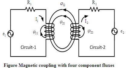
Magnetic coupling between two individual circuits are shown in Figure 2.2. For the purpose of analysis we assume the total flux which is established by (circuit-1 current), namely is divided into two components. One component of is that part which links with circuit-1 but not with circuit-2, namely . The second component of is which links with both circuit-2 and circuit-1. In this similar way the flux established by (circuit-2 current), namely has also two components. One component of is which links only circuit-2 but not with circuit-1. Again another component of is which links both circuit-2 and circuit-1.
Here is a fractional part of, which links with the turns of circuit-2. So is called the mutual flux produced by circuit-1.
In the same way the fractional part of is which links with the turns of circuit-2.
So is called the mutual flux produced by circuit-2.
This is the phenomenon how the magnetic coupling takes place between two individual circuits. This effect can be magnified or amplified through coiling the wire.
Power transfer efficiency of magnetic coupling can be increased by increasing the number of turns in the coil, the strength of the current, the area of cross-section of the coil and the strength of the radial magnetic field. Magnetic fields decay quickly, making magnetic coupling effective at a very short range.
Resonant frequency
Resonance is a phenomenon that causes an object to vibrate when energy of a certain frequency is applied. In physics, resonance is the tendency of a system (usually a linear system) to oscillate with larger amplitude at some frequencies than at others. These are known as the system’s resonant frequencies. At these frequencies, even small periodic driving forces can produce large amplitude oscillations.
Magnetic Resonant Coupling
Magnetic Resonant coupling uses the same principles as inductive coupling, but it uses resonance to increase the range at which the energy transfer can efficiently take place. Resonance can be two types: (a) series resonance and (b) parallel resonance. The principle of these both types of resonance is to get maximum energy transfer same but the methods are quite different.
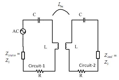
Figure 2.4 shows how the resonance occurs. Here the circuit-1 is called primary circuit and the circuit-2 is called secondary circuit. The energy transfer will occur between these two circuits. The resonant conditions in such circuit either in the primary circuit, when the primary current is in phase with the input voltage, or in the secondary circuit, when the secondary circuit current is in phase with the secondary induced voltage. The former resonance is called primary particular resonance and the latter is a secondary particular resonance. The full resonance occurs when both the primary and the secondary circuits are in the resonant condition.
Resonant energy transfer or resonant inductive coupling is the short distance wireless transmission of energy between two coils that are highly resonant at the same frequency. The equipment to do this is sometimes called a resonant transformer. While many transformers employ resonance, this type has a high Quality Factor and is nearly always air cored to avoid ‘iron’ losses. The coils may be present in a single price of equipment or in separate prices of equipment.
Resonant transfer works by making a coil ring with an oscillating current. This generates an oscillating magnetic field. Because the coil is highly resonant any energy placed in the coil dies away relatively slowly over many cycles; but if a second coil is brought near to it, the coil can pick up most of the energy before it is lost, even if it is some distance away.
Magnetic resonant coupling involves creating an LC resonance, and transferring the power with electromagnetic coupling. Hence, the magnetic coupling can be represented as mutual inductance as in Figure 2.4. represents the characteristic impedance, and is the impedance of the load. In this paper, they are both considered to be the same at . The ohm loss and the radiation loss of the antennas are represented by R.
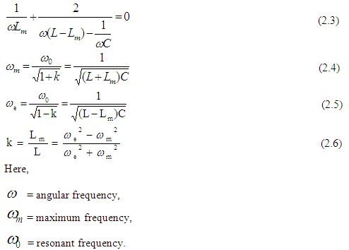
The resonant frequency can be calculated from the equivalent circuit. To satisfy the resonance condition, the reactance of Figure 2.4 must be zero, as in equation (2.3). The condition in equation (2.3) can be satisfied by two resonant frequencies as calculated in equation (2.4) and (2.5). The coupling coefficient k can be calculated from equation (2.4) and (2.5). The coupling coefficient is represented in equation (2.6). It represents the strength of the magnetic coupling between the antennas, which is closely related to factors such as the air gap between the antennas and the obstacles between them.
Summary
Magnetic coupling is an old and well understood method in the field of wireless power transfer. But as the magnetic field decay very quickly, magnetic field is effective only at a very short distance. By applying resonance with in magnetic coupling, the power transfer at a greater distance can be obtained.
Quality-factor
In physics and engineering the Quality factor (Q-factor) is a dimensionless parameter that describes the characteristics of an oscillator or resonator, or equivalently, characterizes a resonance’s bandwidth relative to its center frequency. Higher Q indicates a lower rate of energy loss relative to the stored energy of the oscillator; the oscillations die out more slowly. A pendulum suspended from a high-quality bearing, oscillating in air, has a high Q, while a pendulum in oil has a low one. Oscillators with high quality factors have low damping so that they ring longer.
The bandwidth, of a damped oscillator is shown on a graph of energy versus frequency. The Q factor of the damped oscillator, or filter, is . The higher the Q, the narrower and sharper the peak is. The bandwidth of a damped oscillator is shown on a graph of energy versus frequency.
Sinusoidal signal driven resonators having higher Q factors resonate with greater amplitudes (at the resonant frequency) but have a smaller range of frequencies around that frequency for which they resonate; the range of frequencies for which the oscillator resonates is called the bandwidth. Thus, a high Q tuned circuit in a radio receiver would be more difficult to tune, but would have more selectivity; it would do a better job of filtering out signals from other stations that lie nearby on the spectrum. High Q oscillators oscillate with a smaller range of frequencies and are more stable.
The quality factor of oscillators varies substantially from system to system. Systems for which damping is important (such as dampers keeping a door from slamming shut) have Q = ½. Clocks, lasers, and other resonating systems that need either strong resonance or high frequency stability need high quality factors. Tuning forks have quality factors around Q=1000. The Quality factor of atomic clocks, superconducting RF cavities used in accelerators, and some high-Q lasers can reach as high as 1011 and higher.
The physicists and engineers have been used many alternate quantities to describe how damped an oscillator that are closely related to the quality factor. Important examples include: the damping ratio, relative bandwidth, line width and bandwidth measured in octaves.
The concept of Q factor originated in electronic engineering, as a measure of the “quality” desired in a good tuned circuit or other resonator.
Definition of the Quality factor
There are two separate definitions of the quality factor that are equivalent for high Q resonators but are different for strongly damped oscillators.
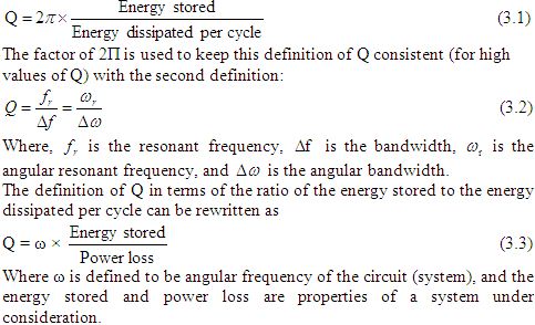
Generally Q is defined in terms of the ratio of the energy stored in the resonator to the energy being lost in one cycle:
Q-factor and damping
The Q factor determines the qualitative behavior of simple damped oscillators. A system with low quality factor (Q < ½) is said to be over damped. Such a system doesn’t oscillate at all, but when displaced from its equilibrium steady-state output it returns to it by exponential decay, approaching the steady state value asymptotically. It has an impulse response that is the sum of two decaying exponential functions with different rates of decay. As the quality factor decrease the slower decay mode becomes stronger relative to the faster mode and dominates the system’s response resulting in a slower system. A second-order low-pass filter with a very low quality factor has a nearly first-order step response; the system’s output responds to a step input by slowly rising toward an asymptote.
A system with high quality factor (Q > ½) is said to be under-damped. Under-damped system combined oscillation at a specific frequency with decay of the amplitude of the signal. Under damped system with a low quality factor (a little above Q = ½) may oscillate only once or a few times before dying out. As the quality factor increases, the relative amount of damping decreases. A high quality bell rings with a single pure tone for a long time after being struck. A purely oscillatory system, such as a bell that rings forever, has an infinite quality factor. More generally, the output of a second –order low pass filter with a very high quality factor responds to a step input by quickly rising above, oscillating around, and eventually converging to a steady- state value.
A system with an intermediate quality factor (Q=½) is said to be critically damped. Like an over-damped system, the output does not oscillate, and does not overshoot its steady-state output (i.e., it approaches a steady-state asymptote). Like an under-damped response, the output of such a system responds quickly to a unit step input. Critical damping results in the fastest response (approach to the final value) possible without overshoot.
Real system specifications usually allow some overshoot for a faster initial response or require a slower initial response to provide a safety margin against overshoot.
In negative feedback systems, the dominant closed-loop response is often well-modeled by a second- order system. The phase margin of the open –loop system sets the quality factor Q of the closed-loop system; as the phase margin decreases, the approximate second-order closed-loop system is made more oscillatory (i.e., has a higher quality factor).
Physical interpretation of Q
Physically, Q is 2Π times the ratio of the total energy stored divided by the energy lost in a single cycle or equivalently the ratio of the stored energy dissipated per one radian of the oscillation.
It is a dimensionless parameter that compares the time constant for decay of an oscillating physical system’s amplitude to its oscillation period. Equivalently, it compares the frequency at which a system oscillates to the rate at which it dissipates its energy.
Where is the resonant frequency, and, the bandwidth, is the width of the range of frequencies for which the energy is at least half its peak value.
The factors Q, damping ratio ζ, and attenuation α are related such that,
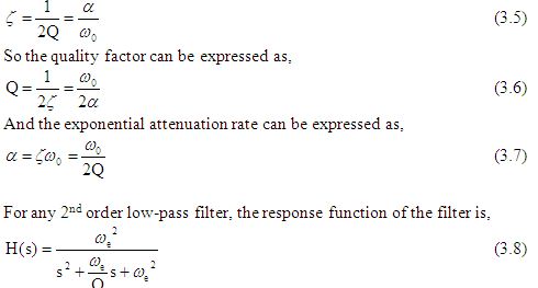
For this system , when Q > 0.5 (i.e.. when the system is under damped), it has two complex conjugate poles that each have a real part of α .That is, the attenuation parameter α represents the rate of exponential decay of the oscillations (e.g. , after an impulse) of the system. A higher quality factor implies a lower attenuation, and so high Q system oscillate for long times. For example, high quality bells have an approximately pure sinusoidal tone for a long time after being struck by a hammer.
Q factor in Electrical systems
For an electrically resonant system, the Q factor represents the effect of electrical resistance and, for electromechanical resonators such as quartz crystals, mechanical friction.
The frequency axis of this symbolic diagram can be linear or logarithmically scaled.
Figure 3.2 shows the definition of bandwidth (B) for a band pass filter. Where, is the centre frequency, is the higher cut-off frequency, and is the lower cut-off frequency. The 0 dB level is the level of the peak of the band pass response, which is not necessarily located at the centre frequency. Also the centre frequency is located at either the arithmetic or geometric mean of the upper and lower cut-offs depending on context and conventions.
Q factor in RLC circuits
In an ideal series RLC circuit and in a turned radio frequency receiver (TRF) the Q factor is:
Where, R, L and C are respectively the resistance, inductance and capacitance of the turned circuit.
For a parallel RLC circuit, the Q factor is the inverse of the series case.
(3.10)
In a parallel RLC circuit where the R is in series with the L, Q is the same. This is the most common circumstance because, for resonators, limiting the resistance of the inductor to improve Q and narrowing the bandwidth is the desired result.
For a circuit where R, L and C are all in parallel, the lower the parallel resistance, the more effect it will have in damping the circuit and thus the lower the Q. In this case the X and R are interchanged. This is useful in filter design to determine the bandwidth.
Summary
Q-factor is a measure of “quality” of a particular resonance. The ratio of the inductance to the resistance of a coil remains constant for different winding arrangements in the same volume and shape. It makes sense to define this value as a figure of merit to distinguish different coil structures. The quality factor Q is defined by this ratio. The voltage, which is induced by the same current in an inductor scales with the frequency and thus the apparent power in the device.
Optimization of Wireless Power Transfer System
The power transfer efficiency versus normalized distance i.e. the ratio of the separation between the coils is a commonly used performance metric for comparing different designs. Because of the low Quality factor (due to the source and load resistances), low coupling of the coils in the two-coil system, impedance mismatching, and power losses in the coils, two-coil-based power transfer suffer from a relatively low power transfer efficiency.
Impedance Matching
In electronics, impedance matching is the practice of designing the input impedance of an electrical load or the output impedance of its corresponding signal source in order to maximize the power transfer and minimize reflections from the load.
The term impedance is used for the resistance of a system to an energy source. For constant signals, this resistance can also be constant. For varying signals, it usually changes with frequency. The energy involved can be electrical, mechanical, magnetic or even thermal. The concept of electrical impedance is perhaps the most commonly known. Electrical impedance, like electrical resistance, is measured in ohms. In general, impedance has a complex value, which means that loads generally have a resistance to the source that is in with a sinusoidal source signal and reactance that is out of phase with a sinusoidal source signal. The total impedance is the vector sum of the resistance and the reactance.
Whenever a source of power with a fixed output impedance, such as an electric signal source, a radio transmitter operates into a load, the maximum possible power is delivered to the load when the impedance of the load (load impedance or input impedance) is equal to the complex conjugate of the impedance of the source (that is, its internal impedance or output impedance). For two impedances to be complex conjugates, their resistances must be equal, and their reactance must be equal in magnitude but of opposite sign.
In low-frequency or DC systems, or in systems with purely resistive sources and loads, the reactances are zero, or small enough to be ignored. In this case, maximum power transfer occurs when the resistance of the load is equal to the resistance of the source.
Power Transfer Efficiency Analysis
The efficiency of the coupled system depends on how much energy is transferred from the transmitter to the receiver circuit.
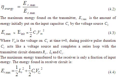
The voltage across the receiver capacitor is defined to be the output of the coupled system. When this output voltage is at maximum, the energy in the capacitor is at maximum. When the energy stored in the capacitor is at maximum, the energy in the receiver can be assumed as maximum.
At maximum voltage level on receiver circuit, current becomes zero and no current flows from the circuit. At this point energy stored in receiver inductor is zero because current is zero. Thus maximized receiver energy is:
To explicitly determine this maximum receiver energy, it is necessary to first determine the output voltage and its maximum value. The load is connected across the receiver capacitance. The total output energy is defined to be the power dissipated by the load integrated over the life time of the output waveform. The output voltage across the load resistor is found by using the equivalent output impedance in a Thevenin equivalent circuit.
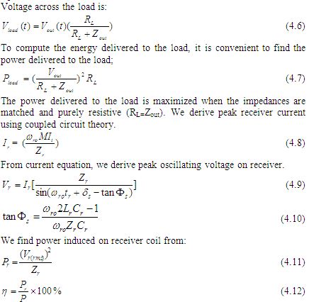
 Where, is the series resistance, is the effective resistance , L is the inductance of coil, Effective Inductance of coil, Cp is the resonating capacitor, CR is the capacitance of the receiver and ESR is the effective series resistance.
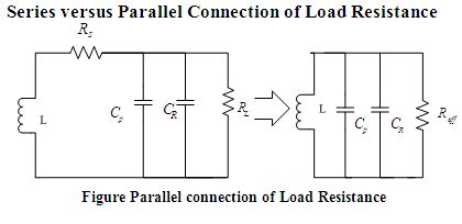
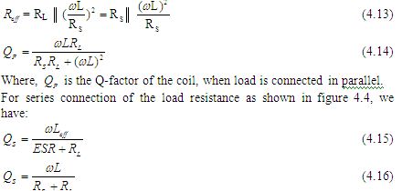
To improve the Q-factor of the load coil, the load resistance can be either attached in series or parallel to resonating capacitor (Cp, refer to Figure-4.3). For parallel connection of the load resistance as shown in Figure 4.4, we have:
High Quality Factor Coil Designing
In case of wireless power transmission, the purpose of the coil is not only to possess inductance but to create a region of space having a definite magnetic flux density.
For the greater efficiency, the coils must possess high quality factor also. To achieve high quality factors coils with low effective series resistance (ESR) are required. The power handling capacity of a coil can be increased by building it from thicker wire. At short-wave frequencies, a phenomenon named skin effect forces all current to flow into the outside layer of metal. As a result, a wire tube will be as effective as the same diameter of solid wire.
Copper loss
Copper loss is the heat produced by electrical currents in the coil. Copper losses are an undesirable transfer of energy, as are core losses, which result from induced currents in adjacent components. The term is applied regardless of whether the coils are made of copper or another conductor, such as aluminum.
Copper Loss = I2R (4.24)
Where, I is the current flowing in the conductor and R the resistance of the conductor.
With high-frequency currents, loss in a coil is affected by proximity effect and skin effect, and cannot be calculated as simply. For low-frequency applications, the power lost can be minimized by employing conductors with a large cross-sectional area, made from low resistivity metals.
AC Resistance
At high frequencies, skin and proximity effect increases the ESR, When direct current is applied to a straight conductor it distributes itself evenly throughout the wire’s cross-sectional area. When an alternating current is applied to a straight conductor, eddy current develop and the current will tend to flow on the surface. As the AC frequency is increased it becomes increasingly difficult for the current to penetrate into the center of the conductor, which flows along the conductor surface (skin). This increases the effective resistance of the wire and is called skin effect and is the major source of resistivity in a high frequency solenoid.
RAC=FACRDC
Where, RAC is the AC resistance, FAC is AC flux and RDC is the DC resistance.
Skin effect is essentially the inability of current to penetrate from the periphery toward the center of a conductor as the frequency is increased. This is a direct result of eddy currents established in the conductor from the changing AC flux (Figure 4.5). The eddy current reinforces current
flow on the conductor’s “Skin”, decreasing exponentially as they move toward the center.
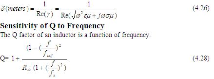
At low frequencies, Q increases with frequency and for > due to the dominance of proximity effect on AC resistance, the Q-factor decreases. To utilize the coil for different operating frequency, it is desirable to have a Q-factor that is not too sensitive to frequency; should be kept sufficiently high so that AC resistance stays small.
Advantages of an Air Core Coil
Its inductance is unaffected by the current is carries. This contrasts with the situation with coils using ferromagnetic cores whose inductance tends to reach a peak at moderate field strengths before dropping towards zero as saturation approaches. Sometime no-linearity in the magnetization curve can be tolerated. Most radio transmitters rely on air coils to prevent the production of harmonics. Air coils are also free of the ‘iron losses’ which affect ferromagnetic cores. As frequency is increased this advantage becomes progressively more important. It provides better Q-factor, greater efficiency, greater power handling and less distortion. Lastly, air coils can be designed to perform at frequencies as high as 1 GHz. Most ferro-magnetic cores tend to be rather lossy above 100 MHz.
Advantages of Copper as Conductor Material
For the circuit presented, such a coil had to be used as the transmitter coil so that it can handle a high amount of current flow. High current flow through the coil causes it is to get heated.
With all metals, electrical conductivity varies with temperature. If a metal becomes over-heated from inadvertent electrical overload, then its conductivity is reduced, which aggravated the temperature situation. Copper is well known for its excellent performance under such adverse conditions.
Copper has the highest electrical conductivity of the commercial metals, except silver. The electrical conductivity of annealed copper at 20oC (68oF) is the standard to which all other metals and alloys are compared. It is arbitrarily established at 100% IACS (International Annealed Copper Standard). Its strength, formability, eases of joining, resistance to creep, high thermal conductivity, and resistance to corrosion are also of equal importance.
For all practical purposes, copper is better than more expensive materials such as silver and gold, and is somewhat better than aluminum. Copper, however, can be more easily oxidized than aluminum. Since the impact of skin effect is that the current will flow on the outside of the conductor, copper should be protected from oxidation by a spray coating such as clear Krylon acrylic spray paint.
Q factor of a Single layer Air Core Coil
The Q factor of an inductor is the ratio of its inductive reactance to its series resonance . The larger the ratio, the better the inductor is.
Where,
f= frequency (Hz)
L= inductances in henries
, is determined by multiplying the length of the wire, used to wind the coil, by the DC resistance per unit length for the wire gage used.
Q changes dramatically as a function of frequency. At lower frequencies, Q is very good because only the DC resistance of the windings (which is very low) has an effect. As frequency goes up, Q will increase up to about the point where the skin effect and the combined distributed capacitance begin to dominate. At the self resonance frequency of the coil Q falls rapidly and becomes 0.
Summary
Resonant based power delivery is an alternative wireless power transfer technique which is used for high power transfer efficiently.
In this chapter a more comprehensive circuit-based model for the system is presented and the effect of each design parameter is analyzed. Step-by-step design procedure was followed to optimize the wireless power transfer systems.
From the analysis it has been demonstrated that, parallel connection of load, maximizing mutual inductance and coupling coefficient, and impedance matching increases the power transfer efficiency.
Block Diagram Representation of Wireless Power Transfer System
The choice of an effective principle for power transfer is necessary for its success. The drawbacks associated with radiative transfer method are more pronounced than its advantages. Therefore an alternate method includes designing the source coil and receiving coil at same resonant frequency for mid range energy transfer so that the distance of energy transmission is of a few times the size of the antennas. Considering the dangers of electric fields on living organisms, the magnetic field is relatively safer and therefore more suitable for transmitting power wirelessly. So the two systems were operated in a strongly coupled magnetic resonance. In this chapter, we have described the block diagram representation of wireless power transfer system. The components used in this block diagram are also described.
Block Diagram of Wireless Power Transfer System
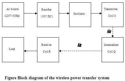
At first an ac source is taken and it is connected with the rectifier. Then the rectifier is connected to the oscillator. Oscillator transfers current to the transmitter coil. A magnetic field is then created between the transmitter coil and receiver coil. The magnetic field energy is transferred to the load without using any wire. An intermediate coil is also used. It is placed in between of the transmitter coil and receiver coil.
AC Source
A power supply is a device that supplies electric power to an electrical load. The term is most commonly applied to devices that convert one form of electrical energy to another, though it may also refer to devices that convert another form of energy (mechanical, chemical, solar) to electrical energy. A regulated power supply is one that controls the output voltage or current to a specific value; the controlled value is held nearly constant despite variations in either load current or the voltage supplied by the power supply’s energy source.
Here a (220V-50Hz) ac source is used.
Rectifier
A rectifier is an electrical device that converts alternating current (AC), which periodically reverses direction, to direct current (DC), which flows in only one direction. The process is known as rectification. Physically, rectifiers take a number of forms, including vacuum tube diodes, mercury arc valves, solid state diodes, silicon controlled rectifiers and other silicon-based semiconductor switches.
Rectifiers have many uses, but are often found serving as components of DC power supplies and high-voltage direct current power transmission systems. Rectification may serve in roles other than to generate direct current for use as a source of power. As noted, detectors of radio signals serve as rectifiers. In gas heating systems flame rectification is used to detect presence of flame.
The simple process of rectification produces a type of DC characterized by pulsating voltages and currents (although still unidirectional). Depending upon the type of end-use, this type of DC current may then be further modified into the type of relatively constant voltage DC characteristically produced by such sources as batteries and solar cells.
Here, bridge rectifier circuit is used.
Oscillator
An electronic oscillator is an electronic circuit that produces a repetitive electronic signal, often a sine wave or a square wave. They are widely used in many electronic devices. Common examples of signals generated by oscillators include signals broadcast by radio and television transmitters, clock signals that regulate computers and quartz clocks, and the sounds produced by electronic beepers and video games.
Oscillators designed to produce a high-power AC output from a DC supply are usually called inverters.
Transmitter Coil
The transmitter coil constitutes of an inductor and capacitor and connected with the transmitter circuit. Here a copper tube is used as an inductor. The parameters of the inductor and capacitor are chosen to produce resonance at a particular frequency.
Intermediate Coil
The intermediate coil constitutes of an inductor and capacitor which is supposes to produce resonance with the magnetic field generated from source resonant circuit in order to receive energy. It also consists of an LED.
Receiver Coil
The receiver coil constitutes of an inductor, a capacitor and a LED. Here LED is used as the load.
Summary
In this chapter the block diagram representation of wireless power transmission is described. This block diagram represents the step by step process to design the wireless power transfer system. We can get a brief explanation of ac source, oscillator and rectifier from here.
Components
Different components are used during the implementation of the wireless energy transfer model. These are resistor, capacitor, MOSFETs, radio frequency chokes etc. The power that is transmitted has to be applied across the LC combination. So, all these components should be added to the transmitter and receiver circuit.
Description
A Power MOSFET is a specific type of Metal Oxide Semiconductor Field-Effect Transistor (MOSFET) designed to handle large amounts of power. Compared to the other power semiconductor devices (IGBT, Thyristor), its main advantages are high commutation speed and good efficiency at low voltages. It shares with the IGBT an isolated gate that makes it easy to drive. It was made possible by the evolution of CMOS technology, developed for manufacturing Integrated circuits in the late 1970s. The power MOSFET shares its operating principle with its low-power counterpart, the lateral MOSFET.
The power MOSFET is the most widely used low-voltage (i.e. less than 200 V) switch. It can be found in most power supplies, DC to DC converters, and low voltage motor controllers.
We used an N-channel HEXFET power MOSFET in our project. It is used as a low voltage switch.
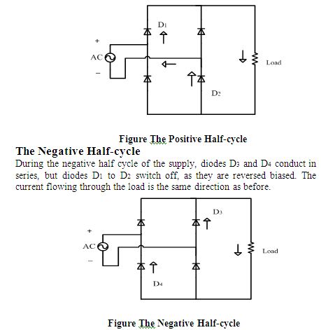
The Bridge Rectifier
The Bridge rectifier rectifies that source voltage (220V, 50Hz) to 18V DC. It uses 4 individual rectifying diodes connected in a “bridged” configuration to produce the desired output but does not require a special centre tapped transformer, thereby reducing its size and cost. The single secondary winding is connected to one side of the diode bridge network and the load to the other side as shown in figure 6.2.
The 4 diodes labeled to are arranged in “series pairs” with only two diodes conducting current during each half cycle (Figure: 6.2).
The positive Half-cycle
During the positive half cycle of the supply, diodes D1 to D2 conduct in series while diodes D3 and D4 are reversed biased and the current flows through the load as shown in figure 6.3.
The Smoothing Capacitor
The single phase half-wave rectifier produces an output wave every half cycle and that it was not practical to use this type of circuit to produce a steady DC supply. The full-wave bridge rectifier however, gives a greater mean DC value (0.673Vmax) with less superimposed ripple while the output waveform is twice that of the frequency. Therefore, its average DC output level can be increased even higher by connecting a suitable smoothing capacitor across the output of the bridge circuit as shown in figure 6.5.
The smoothing capacitor converts the full-wave rippled output of the rectifier into a smooth DC output voltage. Two important parameters are considered while choosing a suitable capacitor. These are –
- It’s working voltage, which must be higher than the no-load output of the rectifier.
- It’s capacitance value, which determines the amount of ripple that will appear superimposed on top of the DC voltage. If the value of the capacitance is too low, then the capacitor will have little effect.
The main advantages of a full-wave bridge rectifier is that it has a smaller AC ripple value for a given load and a smaller reservoir or smoothing capacitor that an equivalent half-wave rectifier. Therefore, the fundamental frequency of the ripple voltage is twice that of the AC supply frequency (100Hz) where for the half-wave rectifier it is exactly equal to the supply frequency (50Hz).
The amount of ripple voltage that is superimposed on top of the DC supply voltage by the diodes can be virtually eliminated by adding a much improved π-filter (pi-filter) to the output terminals of the bridge rectifier. This type of low-pass filter consists of two smoothing capacitors, usually of the same value and a choke or inductance across them to introduce a high impedance path to the alternating ripple component.
Another more practical and cheaper alternative is to use a 3-terminal voltage regulator IC, such as a LM7805 which can reduce the ripple by more than 70dB while delivering over lamp of output current.
The Oscillator Circuit
A Royer Oscillator is an electronic oscillator which has the advantages of simplicity, low component count, sinusoidal waveforms and easy transformer isolation. It was first described by George H. Royer in December 1954 in Electrical Manufacturing. The Basic Royer Oscillator is shown in Figure 6.6.
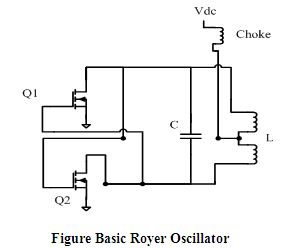
The circuit consists of a saturable core transformer with a center tapped primary winding, a feedback winding and a secondary winding. A capacitor is connected across the primary to make a resonant circuit. Each half of the primary is driven by a transistor in a push-pull configuration. The feedback winding couples a small amount of the transformer flux back in to the transistor bases to provide positive feedback, generating oscillation. The oscillation frequency is determined by the maximum magnetic flux density, power supply voltage, and inductance of the primary winding.
The prototype oscillator circuit designed for the wireless power transfer system is a modified Royer oscillator. This oscillator circuit is incredibly simple yet a powerful design. Very high oscillating current can be achieved with this circuit depending on the semiconductor used. Here high current is necessary to increase the strength of the magnetic field. Although, Insulated Gate Bipolar Transistors (IGBT) are recommended for this type of oscillator, but IGBTs has limitations in high frequencies.
Oscillator Circuit Operation
The circuit consists of with two chokes labeled and , two semiconductors (Here N-channel enhancement power-MOSFETs) labeled and , a resonating capacitor labeled C and inductor (here the transmitter coil) labeled L. Cross-coupled feedback is provided via the diodes and . , and , are the biasing network for MOSFETs and (Figure 6.7).
When power is applied, DC current flows through the two sides of the coil and to the transistor’s drain. At the same time the voltage appears on both gates and starts to turn the transistors ON. One transistor is invariably a little faster than the other and will turn ON more. The added current flowing in that side of the coil does two things. One, it takes away drive from the other transistor. Two, the auto-transformer action impresses a positive voltage on the conducting transistor, turning it hard ON. The current would continue to increase until the coil (transformer) saturates. The resonating capacitor C causes the voltage across the primary to first rise and then fall in a standard sine wave pattern.
Assuming that turned on first, the voltage at the drain of ’s will be clamped to near ground while the voltage at ’s drain rises to a peak and then fall as the tank formed by the capacitor and the coil primary oscillator through one half cycle.
The oscillator runs at the frequency determined by the inductance of the coil, the capacitor value and to a lesser extent, the load applied to the secondary (Source Coil).
The operating frequency is the familiar formula for resonance,
Oscillator Components
Components used are given in the table 6.1
Table 6.1 Oscillator Components
| Component’s Name | Component’s Value or code |
| Voltage Source, | 18V |
| Capacitor, C1 | 100nF |
| Capacitor, C | 60nF |
| Resistor, R1 | 100 ohm |
| Resistor, R2 | 100 ohm |
| Resistor, R3 | 10k ohm |
| Resistor, R4 | 10k ohm |
| Diode, D1 | 1N4142 |
| Diode, D2 | 1N4142 |
| MOSFET, Q1 | IRF1010 |
| MOSFET, Q2 | IRF1010 |
| Radio Frequency Choke, L1 | 100µH |
| Radio Frequency Choke, L2 | 100µH |
| Transmitter coil, L | 187.5 nH |
Source Coil, Secondary coil and Load coil
For the experiment, the source coil, intermediate coil and the load coil was constructed using 0.6mm copper tube with radius 6.5 inches.
Radio Frequency Choke
Choke is an inductor designed to block (have a high reactance to) higher frequencies in an electrical circuit while passing signals of much lower frequency or direct current.
Uses of RF Chokes
Choke coils are inductances that isolate AC frequency currents from certain areas of a radio circuit, chokes depend upon the property of self-inductance for their operation. They can be used to block alternating current while passing direct current (contrast with capacitor).
Common mode choke coils are useful in a wide range of prevention of electromagnetic interference (EMI) and radio frequency interference (RFI) from power supply lines and for prevention of malfunctioning of electronic equipment. They pass differential currents (equal but opposite), while blocking common-mode currents.
We have used RF chokes in the transmitter circuit.
Types and Construction
Chokes used in radio circuits are divided into two classes – those designed to be used with audio frequencies, and the others to be used with radio frequencies. Audio frequency coils, usually called A.F. chokes, can have ferromagnetic iron cores to increase their inductance. Chokes for higher frequencies have iron powder or ferrite cores (Ferrite bead). Chokes for even higher frequencies have non-magnetic cores and low inductance simulating the effects of an air-core.
Summery
In order to transmit power wirelessly via magnetic resonant coupling all these components has to be used. The design of the transmitter and receiver circuit depends on these components. The overall efficiency of the experiment should be decreased if any one of these components was not be used.
Design and Implementation of Wireless Power Transfer System
The problem with many of today’s electronic devices, such as cell phones, laptop computers and personal digital organizers, is that despite their probability and ability to communicate wirelessly, these devices still require regular charging – usually by plugging into a wall outlet. The ability to provide power for these and other electric devices wirelessly would greatly increase their portability and accessibility for the public.
An efficient method for wireless power transfer would also enable advances in such diverse areas as embossed computing, mobile computing, sensor networks and micro robotics. The need to minimize the energy consumption is often the main design driver in applications where devices need to operate without ethered. Energy consumption often restricts or severely limits functionally in such applications. The work described in this paper is motivated by potential application of magnetic resonant coupling as a means for wireless power transfer from a source coil to a single load. Through simple experimental setups and corresponding circuit models, we address issues that are involved in applying the basic mechanism to a single receiver.
Theoretical Model
Our experimental realization of the scheme consists of three coils that are tuned at the same frequency. An oscillating circuit is connected with a source coil S. Coil S is coupled resonant inductively to an intermediate Coil Q; which is in turn coupled resonant inductively to a load carrying Coil R. The coils are made of an electrically conducting copper pipe of cross-sectional radius a wound into a helix of single turn, radius r.
Then a radio frequency oscillating signal is passed through coil S, it generates an oscillating magnetic field, perpendicular to the coil S. The intermediate coil Q is placed near to the Coil S, which is tuned at the same frequency through the inductance of the coil and a resonating capacitor . The coil Q being in the area of the magnetic field generated by coil S, receives power. The coil Q turn generates its own oscillating magnetic field without any resistive load. The advantage of using this coil is that it is completely separated from the source internal resistance. This increases the Q-factor, allowing greater power to be mediated. In other words, the coil Q becomes the source of the system.
The load coil R, tuned at the same resonant frequency, receives the power through the magnetic field generated by the intermediate coil Q.
Power Transfer Model of Wireless Power Transfer System
The equivalent circuit diagram of power transfer model is given in figure 7.2. The power transfer occurs from coil S to coil R. The power loss in coil Q is neglected here, since the coil Q has a very small resistance.
Experimental set-up and design
In the practical experiment, 4 different set-ups are made.
- An 18V transformer is used as the power supply. This transformer is connected with the rectifier circuit.
- An oscillator circuit is used as the transmitter.
- Two copper coil with capacitor connected is used as the receiver.
- A LED is used as the load which is connected with the receiver.
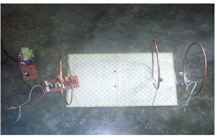
Figure Implementation of wireless power transfer system
The total implementation of the project is given below–
- The 18V transformer with rectifier circuit is connected to the transmitter or oscillator circuit.
- The RF chokes present in the transmitter circuit creates a magnetic field.
- The receiver coil which constitutes of an inductor and capacitor is placed at a distance from the transmitter circuit.
- The LC circuit of the receiver coil produces resonance with the magnetic field generated from the source and transmitter circuit.
- When the switching is performed, the LED we have used as a load lit up to a maximum distance of 60 centimeter with voltage measured 2.2 volts.
Summary
The theoretical model and circuit implementation of the wireless power transfer system was designed based on the concept of magnetic resonant coupling. Various optimization factors were also considered while designing the whole system. Due to generalized approach, presented wireless power transfer system can be optimized for new design constraints or for different applications.
Performance and Analysis
Wireless power transfer is a very efficient project. But the primary concern with exposure to this new technology is its potential risk of using high frequency radio signal. The approach suggested by Tesla, included strong electric field radiation which was one of the prime reasons why his theory is not incorporated in modern technology. A different measurement was taken while the wireless energy transfers. A voltage source and resonant frequency is used while taking the measurements. The power transfer efficiency is to be determined in this process and we can know how much the power dissipated.
Efficiency and Evaluation of Power Losses
Measurements have been taken providing 30V with resonant frequency 1.5 MHz across the transmitter and without the intermediate coil.
1) A 3 watt bulb lit up at its full strength at a distance of 17 centimeter with voltage measured 15 volts.
2) A 3 watt bulb lit up to a maximum distance of 41 centimeter with voltage measured 10 volts.
3) A LED lit up to a maximum distance of 70 centimeter with voltage measured 2.2 volts.
4) Voltage measured at a distance 5.25 meter was 3 milli-volts.
3 watt bulb (without intermediate coil):
Table Theoretical and practical comparison for 3 watt bulb
(Without intermediate coil)
| Distance | Output Voltage (Theoretical) | Output Voltage (Practical) |
| 17cm | 17 volts | 15 volts |
| 25cm | 15 volts | 13.1 volts |
| 34cm | 12 volts | 11 volts |
| 41cm | 11 volts | 10 volts |
LED (without intermediate coil):
Table Theoretical and practical comparison for LED
(Without intermediate coil)
| Distance | Output Voltage (Theoretical) | Output Voltage (Practical) |
| 31cm | 5.7 volts | 4.1 volts |
| 43cm | 4.8 volts | 3.3 volts |
| 58cm | 4.1 volts | 2.9 volts |
| 70cm | 3.5 volts | 2.2 volts |
Measurements have been taken with intermediate coil placed in between transmitter and receiver at a distance 12 cm apart from the transmitter.
1) A 3 watt bulb lit up at its full strength at a distance of 34 centimeter with voltage measured 15 volts.
2) A 3 watt bulb lit up to a maximum distance of 61 centimeter with voltage measured 10 volts.
3) A LED lit up to a maximum distance of 91 centimeter with voltage measured 2.2 volts.
4) Voltage measured at a distance 5.90 meters and the voltage measured 6 milli-volts.
3 watt bulb (with intermediate coil):
Table Theoretical and practical comparison for 3 watt bulb
(With intermediate coil)
| Distance | Output Voltage (Theoretical) | Output Voltage (Practical) |
| 34cm | 18 volts | 15 volts |
| 45cm | 16.5 volts | 14 volts |
| 54cm | 13 volts | 12.4 volts |
| 61cm | 11 volts | 10 volts |
LED (with intermediate coil):
Table Theoretical and practical comparison for LED
(With intermediate coil)
| Distance | Output Voltage (Theoretical) | Output Voltage (Practical) |
| 51cm | 4.5 volts | 3.7 volts |
| 64cm | 4.1 volts | 3.4 volts |
| 78cm | 3.6 volts | 2.9 volts |
| 91cm | 2.7 volts | 2.2 volts |
For the experimental setup with a single receiver, the root mean square (rms) voltage across the transmitter is 21.2V. The output rms voltage across a 192-Ω resistive load 34cm away from the coil is 10.6V.
The difference between supplied and received power for the system with a single receiver is accounted for power dissipation in resistances.
50% of the power that leaves the terminals of the actual source (ideal source in series with internal resistance) is delivered to the load resistance.
Analysis
The dominant loss occurs in the internal source resistance. This loss occurs whenever a source delivers power to a load, whatever through wires or through a wireless power transfer method. The high internal resistance of the oscillator, used here only for concept demonstration, can be significantly reduced by using a more practical power source. Approximately half remaining power is delivered to the load resistance, with dissipation in the source coil resistance, the largest loss beyond the actual source terminals. By using an intermediate coil close to the source coil increases the Q-factor to a great extent. The intermediate coil takes up most of the power from the source coil and delivers to the load coil. The Q-factor increases as the intermediate coil does not have source internal resistance in it. Thus the power transfer efficiency and the power transfer range increases significantly.
Summery
Apart from losses due to non-ideal characteristics of the inductor and capacitor, radiation loss and ohmic loss; the total power transmitted might not be received because of the loading effect of the receiver which causes the system to “de-tune” from resonance and weakening the coupling factor. Also wave attenuation occurs when it passes through a lossy dielectric medium (free space, air). If the effect of the losses can be minimized then the efficiency of the overall system can be improved to desired levels.
Discussions
In our project the main goal was to design and implement a system that transmits power without wire. In this purpose, a transmitter circuit was implemented. At the end of the transmitter circuit an antenna was connected, which transmits the power. Another antenna was used to receive the power wirelessly from the transmitter circuit. In this project hollow copper pipes were used as antenna, because it has high Q-factor and high power handling performance.
It requires a huge task to implement the whole project. During implementation a number of remarkable problems have been faced and have been solved as well. Though these implementation sessions requires patience, it made real joy after successful solution.
Problems and Solutions
The Problems that were faced during the testing period as well as the solution are given below:
At the inaugural state project, it has to overcome some hurdles to take the decision of development considering the lowest consumption of implementation.
Since efficient midrange wireless power transmission is a recent technology, there is not enough information available about this technology. The work has been done in this project is totally new and different than any other power transmission method.
It was at first thought that in the circuit Vacuum Tube transistors would be used which provides much higher power than the typical power MOSFETs. Later this idea was eliminated as vacuum could not be found in the shops available.
For the oscillator circuit, low ESR polypropylene capacitors are highly recommended to handle the high current flowing through the LC tank. Moreover, other type of capacitor creates high spikes in the sinusoidal wave at the LC tank circuit and effects the MOSFETs. However, Mylar capacitors at first were used which has polyester as the dielectric. The circuit was found unstable with this type of capacitor. Later MKP capacitors were used which performed much better.
Various high speed n-channel MOSFETs was experimented. MOSFETs with low drain to source on resistance and higher power dissipation was found to perform better in the circuit.
At first, the transmitter circuit did not oscillate; instead it shorted the power supply and one MOSFET and inductor heated up rapidly. Later it was found short circuit that was caused by power supply voltage which was rising too slowly on power-up. This was solved by using a switch on the low voltage side that was placed between the oscillator circuit and the rectifier.
Another problem faced when the oscillator circuit started to oscillate so that very little power was available on the load coil. Because the receiver coil was slightly out of resonance, it could not pick up the power properly. This was solved by building both LC-tank circuits with identical loops and capacitances, so that 3rd of the circuits have the same resonant frequency.
Cost of the project
Table Cost of the Project
| Name | Quantities | Cost (Tk.) |
| 18V Transformer | 1 | 1000 |
| Resistor(100 ohm) | 4 | 40 |
| Resistor(10k ohm) | 4 | 40 |
| Diode(1N4142) | 8 | 200 |
| Capacitor(100nF) | 4 | 80 |
| Capacitor(60nF) | 4 | 80 |
| RF Choke | 3 | 900 |
| MOSFET | 4 | 400 |
| Copper tube | 3 | 600 |
| LED bulb | 10 | 100 |
Total 3840
Suggestions for future work
Our circuit is just a trivial representation of the wireless power transfer concept. Suggestions for the future works are given below-
- To transmit the power to a greater distance a high power radio frequency amplifier connected with an oscillator is needed. But the construction of the bulky RF power amplifier requires much time and patience.
- High power vacuum tube transistor amplifier with high current will make the system more efficient.
- The receiver coil can also be fabricated on a PCB board in order to attach with electronic gadgets.
- A layer of silver coat can also be applied over the conductor material in order to decrease the surface resistance and increase the conductivity.
Further effort on this same project can yield some real solutions that can solve the problem we faced. The knowledge of this project will help those who want to design a wireless power transmission.
Conclusion
The goal of this project was to design and implement a wireless power transfer system via magnetic resonant coupling. After analyzing the whole system step by step for optimization, a system was designed and implemented. Experimental results showed that significant improvements in terms of power-transfer efficiency have been achieved. Measured results are in good agreement with the theoretical models.
We have described and demonstrated that magnetic resonant coupling can be used to deliver power wirelessly from a source coil to a load coil with an intermediate coil placed between the source and load coil and with capacitors at the coil terminals providing a simple means to match resonant frequencies for the coils. This mechanism is a potentially robust means for delivering wireless power to a receiver from a source coil.
We have used an intermediate coil in our project. It is placed in between the transmitter coil and receiver coil. The intermediate coil receives power from the transmitter coil. The distance is increased by using this coil. It consists of capacitor, inductor and a receiver load (LED or Bulb). We have got output voltage 2.2 volts and maximum distance covered is 91cm by using a LED as the load of the intermediate coil. We also have got output voltage 10 volts and maximum distance covered is 41cm by using a 3 watt bulb as the load of the intermediate coil. Intermediate coil makes the power transfer more efficient.
We have achieved that the prototype of the system was successful at transferring a significant amount of power wirelessly up to a certain range. This method can be made commercially feasible if the non-ideal conditions are taken care by substitution with external components. This work lays the foundation for wireless power technology to be implemented in commercial product, for instance charging the battery of the laptops, cell phone, PDA and all kinds of portable devices or supplying power to personal computers, lamps, sensors and other product wirelessly.