Scope of human life in the coming hundred years
Mankind has recently enhanced its living standard and its population in an explosive way. In fact, the human population quadrupled and primary power consumption increased 16-fold [1] during the 20th century. The consumption of energy, food, and material resources is predicted to increase 2.5 fold in the coming 50 years. As a result of our efforts for better life, we have come to face, in this 21st century, serious global issues threatening our safe life or even our existence itself on our mother planet Earth. These are issues such as global warming, environmental degradation, declining nutrition on land and sea from rising CO2, and rapid decrease of fossil reservoir. Since the living standard and the population of developing countries are increasing continuously, the demand of energy will be several times larger than that of today’s requirement by 2050.
1.2 Energy demands in the next 50 years
One primary power source at present comes from fossil fuels such as oil, coal and natural gas. However, the fossil fuels have two serious factors that prevent them from being used for as a long-term primary power source. One is their limited amount; they will not last long if used at the same or higher pace than that of today. The other is that they emit carbon dioxide, a green house gas, which causes global warming. [9]
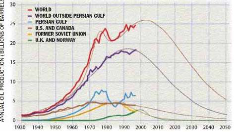
Fig.1.1. Global production of oil. Lighter lines are predictions. [2]
On Nov. 9, 2004, Forbes reported that Russian oil exports may decrease within two years.[3] “Further growth is possible only if price trends are good,” a Russian expert said. Arabicnews.com reported that a sharp decrease in Syria’s light crude oil exports is expected [4] on Nov. 17. Such decrease of oil production is not surprising. M. K. Hubbert predicted in 1956 that crude oil production from U.S. (except Alaska) would crest in 1969. Figure 1.1 depicts the annual oil productions. The lighter lines are predictions according to Campbell and Laherrere’s model, based in part on multiple Hubbert curves. [2] US and Canadian oil indicated by the brown line peaked in 1972 as predicted by Hubbert. Global annual oil production shown in the redline, recovered after falling in 1973 and 1979, but a more permanent decline is seen in recent years. Production in the former Soviet Union (yellow) has fallen 45 percent since 1987. A crest in the oil produced outside the Persian Gulf region (purple) now appears imminent. Figure1.2 illustrates recent trends of the production that supports the prediction.
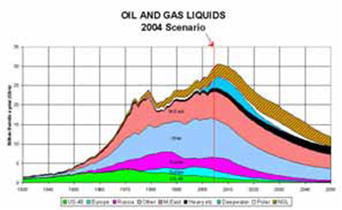
Fig.1.2. Oil and gas liquids 2004 scenario. [5]
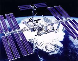
A solar power satellite, or SPS or Power sat, as originally proposed would be a satellite built in high Earth orbit that uses microwave power transmission to beam solar power to a very large antenna on Earth. Advantages of placing the solar collectors in space include the unobstructed view of the Sun, unaffected by the day/night cycle, weather, or seasons [5]. It is a renewable energy source, zero emission after putting the solar cells in orbit, and only generates waste as a product of manufacture and maintenance. However, the costs of construction are very high, and SPS will not be able to compete with conventional sources (at current energy prices) unless at least one of the following conditions is needed. Sufficiently low launch costs can be achieved A determination (by governments, industry, …) is made that the disadvantages of fossil fuel use are so large they must be substantially replaced. Conventional energy costs increase sufficiently to provoke serious search for alternative energy
1.3 An SPS essentially consists of three parts:
* a means of collecting solar power in space, for example via solar cells or a heat engine
* a means of transmitting power to earth, for example via microwave or laser
* a means of receiving power on earth, for example via a microwave antennas (rectenna)
The space-based portion will be in a freefall, vacuum environment and will not need to support itself against gravity other than relatively weak tidal stresses. It needs no protection from terrestrial wind or weather, but will have to cope with space-based hazards such as micrometeorites and solar storms.
1.4 Sustainable energy Sources
In spite of environmental issues and depletion of their resources, it is an undeniable fact that modern society heavily relies on the fossil fuels. According to International Energy Agency, fossil fuels provide about 80% of the total primary energy supply, as depicted in
for our children, we need to establish science and technology for a sustainable society. Such science and technology can be called Green Science and Technology (GST). Technology for stabilization of the carbon dioxide emissions is one of the key elements of the GST and requires development of primary energy sources that do not emit carbon dioxide to the atmosphere or that are renewable. Such sustainable energy technologies include terrestrial solar energy, hydropower energy, wind energy, and other energy systems based on natural resources.
Solar energy conversion (solar photons to DC current)
Two basic methods of converting photons to electricity have been studied, solar dynamic (SD) and photovoltaic (PV). SD uses a heat engine to drive a piston or a turbine which connects to a generator or dynamo. Two heat cycles for solar dynamic are thought to be reasonable for this: the Brayton cycle or the Stirling cycle. Terrestrial solar dynamic systems typically use a large reflector to focus sunlight to a high concentration to achieve a high temperature so the heat engine can operate at high thermodynamic efficiencies; an SPS implementation will be similar. A major advantage of space solar is the ease with which huge mirrors can be supported and pointed in the freefall and vacuum conditions of space. They can be constructed from very thin aluminum or other metal sheets with very light frames, or from materials available in space (eg, on the Moon’s surface). PV uses semiconductor cells (e.g., silicon or gallium arsenide) to directly convert sunlight photons into voltage via a quantum mechanical mechanism which evades the thermodynamic limitations on heat engines. Photovoltaic cells are not perfect in practice as material purity and processing issues during production affect performance; each has been progressively reduced for some decades. These are commonly known as “solar cells”, and will likely be rather different from the glass pane protected solar cell panels familiar to many which are in current terrestrial use. They will, for reasons of weight, probably be built in a membrane form not suitable to terrestrial use where the considerable gravity loading imposes structural requirements on terrestrial implementations. It is also possible to use Concentrating Photovoltaic (CPV) systems, which like SD are a form of existing terrestrial Concentrating Solar Energy approaches which convert concentrated light into electricity by PV, again avoiding the thermodynamic constraints which apply to heat engines. On Earth, these approaches use solar tracking systems, mirrors, lenses, etc to achieve high radiation concentration ratios and are able to reach efficiencies above 40% Concentrating Photovoltaic Technology. Because their PV area is rather smaller than in conventional PV, the majority of the deployed collecting area in CPV systems is mirrors, as with most SD systems. They share the advantages of building and pointing large (simple) mirror arrays in space as opposed to more complex PV panels.
2.1 Comparison of PV, CPV, and SD
The main problems with non-concentrating PV are that PV cells continue to be more expensive relative to the other approaches, and require a relatively large area to be acceptable for a significantly sized power station. In addition, semiconductor PV panels will require a relatively large amount of energy to manufacture; amorphous-silicon designs require much less energy to produce but have been substantially less efficient. CPV designs with a small area of 40%+ efficient cells and large reflector area are expected to be less expensive to produce. As well, the materials used in some PV cells (eg, gallium and arsenic) seem to be less common in lunar materials than is silicon; this may be significant if lunar manufacturing is involved. SD is a more mature technology, having been in widespread use on Earth in many contexts for centuries. Both CPV and SD systems have more severe pointing requirements than PV, because most proposed designs require accurate and stable optical focus. If a PV array orientation drifts a few degrees, the power being produced will drop a few percent. If an SD or CPV array orientation drifts a few degrees, the power produced will drop very quickly, perhaps to near zero. Aiming reflector arrays requires much less energy in space than on Earth, being without terrestrial wind, weather, and gravitation loads, but it has its own problems of gyroscopic action, vibration, limits on usable reaction mass (though electrically powered gyros would avoid that problem), solar wind, and meteorite strikes on control mechanisms. Currently, PV cells weigh between 0.5kg/kW and 10kg/kW depending on design. SD designs also vary but most seem to be heavier per kW produced than PV cells and thus have higher launch costs, all other things being equal. CPV should be lighter; since it replaces the thermal power plant (except for a radiator for waste heat) with a much lighter PV array.
2.2 Working lifetime
The lifetime of a PV based SPS is limited mainly by the ionizing radiation from the radiation belts and the Sun. Without a protection method, this is likely to cause the cells to degrade by about a percent or two per year. Deterioration is likely to be more rapid during periods of high exposure to energetic protons from solar particle outburst events . If some practical protection can be designed, this also might be reducible (eg, for a CPV station, radiation and particle shields for the PV cells — out of the energy path from the mirrors, of course). Lifetimes for SD based SPS designs will be similarly limited, though largely for structural or mechanical considerations, such as micrometeorite impact, metal fatigue of turbine blades, wear of sliding surfaces (although this might be avoidable by hydrostatic bearings or magnetic bearings), degradation or loss of lubricants and working fluids in vacuum, from loss of structural integrity leading to impaired optical focus amongst components, and from temperature variation extremes. As well, most mirror surfaces will degrade from both radiation and particle impact, but such mirrors can be designed simply (and so to be light and cheap), and replacement may be practical. In either case, another advantage of the SPS design is that waste heat developed at collection points is re-radiated back into space, instead of warming the adjacent local biosphere as with conventional sources, though some care will likely be required to provide for the radiation of this waste heat. Thus thermal efficiency will not be in itself an important design parameter except insofar as it affects the power/weight ratio via operational efficiency and hence pushes up launch costs. (For example SD may require larger waste heat radiators when operating at a lower efficiency). Earth based power handling systems must always be carefully designed, for both economic and purely engineering reasons, with operational thermal efficiency in mind. One useful aspect of the SPS approach is that, at the end of life, the material does not need to be launched a second time, at least in principle. In theory, it would be possible to recycle much of the satellite ‘on-site’, potentially at a significantly lower cost than launching an SPS as new. This might allow a very expensive launch cost to be paid for over multiple satellite lifetimes, but does require an in orbit re-processing facility which doesn’t currently exist.
2.3 Energy payback
Clearly, for an SPS system (including manufacture, launch and deployment) to provide net power it must repay the energy needed to construct it. Solar satellites can pay back the lift energy in a remarkably short time. It takes 14.75 kWh/kg for a 100% efficiency system to lift a kg from the surface of the earth to GEO; no such launch system exists and so energy costs are always higher. If the satellite generated a kW with 2kg of mass, the payback time would be 29.5 hours. Assuming a much less efficient (and more realistic) 3% efficient rockets, the energy payback time is only extended to about 6 weeks for such an SPS. For current silicon PV panels, production energy requirements are relatively high, and typically three-four years of deployment in a terrestrial environment is needed to recover this energy. With SPS, net energy received on the ground is higher (more or less necessarily so, if the system to be worth deploying), so this energy payback period would be reduced to about a year. Thermal systems, being made of conventional materials, are more similar to conventional power stations and are likely to be less energy intensive during manufacture. They would be expected to give quicker energy break even, depending on construction technology. The relative merits of PV vs SD is still an open question. Clearly, for a system (including manufacture, launch and deployment) to provide net power it must repay the energy needed to construct it. For current silicon PV panels this is relatively high. With an SPS, the net energy received on the ground is higher so this energy payback period would be somewhat reduced; however an SD based SPS, being made of conventional materials, are more similar to conventional power stations and are likely to be less energy intensive during production and would be expected to give a quicker energy break even, depending on construction technology and other variations.
2.4 Wireless power transmission to the Earth
Wireless power transmission was early proposed to transfer energy from collection to the Earth’s surface. The power could be transmitted as either microwave or laser radiation at a variety of frequencies depending on system design. Whatever choice is made, the transmitting radiation would have to be non-ionizing to avoid potential disturbances either ecologically or biologically if it is to reach the Earth’s surface. This established an upper bound for the frequency used, as energy per photon, and so the ability to cause ionization, increases with frequency. Ionization of biological materials doesn’t begin until ultraviolet or higher frequencies so most radio frequencies will be acceptable for this. William C. Brown demonstrated in 1964 (on air — Walter Cronkite’s CBS News program), a microwave-powered model helicopter that received all the power it needed for flight from a microwave beam. Between 1969 and 1975, Bill Brown was technical director of a JPL Raytheon program that beamed 30 kW of power over a distance of 1 mile at 84% efficiency. To minimize the sizes of the antennas used, the wavelength should be small (and frequency correspondingly high) since antenna efficiency increases as antenna size increases relative to the wavelength used. More precisely, both for the transmitting and receiving antennas, the angular beam width is inversely proportional to the aperture of the antenna, measured in units of the transmission wavelength. The highest frequencies that can be used are limited by atmospheric absorption (chiefly water vapor and CO2) at higher microwave frequencies. For these reasons, 2.45 GHz has been proposed as being a reasonable compromise. However, that frequency results in large antenna sizes at the GEO distance. A loitering stratospheric airship has been proposed to receive higher frequencies (or even laser beams), converting them to something like 2.45 GHz for retransmission to the ground. This proposal has not been as carefully evaluated for engineering plausibility as have other aspects of SPS design; it will likely present problems for continuous coverage
2.5 Spacecraft sizing
The size of an SPS will be dominated by two factors. The size of the collecting apparatus (eg, panels, mirrors, etc) and the size of the transmitting antenna which in part depends on the distance to the receiving antenna. The distance from Earth to geostationary orbit (22,300 miles, 35,700 km), the chosen wavelength of the microwaves, and the laws of physics, specifically the Rayleigh Criterion or Diffraction limit, used in standard RF (Radio Frequency) antenna design will all be factors. For best efficiency, the satellite antenna should be circular and for the probable microwave wavelength, about 1 kilometers in diameter or larger; the ground antenna (rectenna) should be elliptical, 10km wide, and a length that makes the rectenna appear circular from GSO. (Typically, 14km at some North American latitudes.) Smaller antennas would result in increased losses to diffraction/sidelobes. For the desired (23mW/cm²) microwave intensitythese antennas could transfer between 5 and 10 gigawatts of power. To be most cost effective, the system should operate at maximum capacity. And, to collect and convert that much power, the satellite would require between 50 and 100 square kilometers of collector area (if readily available ~14% efficient monocrystalline silicon solar cells were deployed). State of the art (currently, quite expensive, triple junction gallium arsenide) solar cells with a maximum efficiency of 40.7% reduce the necessary collector area by two thirds, but would not necessarily give overall lower costs for various reasons. For instance, these very recently demonstrated variants may prove to have unacceptably short lifetimes. In either cases, the SPS’s structure would be essentially kilometers across, making it larger than most man-made structures here on Earth. While almost certainly not beyond current engineering capabilities, building structures of this size in orbit has not yet been attempted.
2.5.1 LEO/MEO instead of GEO
A collection of LEO (Low Earth Orbit) space power stations has been proposed as a precursor to GEO (Geostationary Orbit) space power beaming system(s). There would be advantages, such as much shorter energy transmission path lengths allowing smaller antenna sizes, lower cost to orbit, energy delivery to much of the Earth’s surface (assuming appropriate antennas are available), etc. And disadvantages, including constantly changing antenna geometries, increased debris collision difficulties, many more power stations to provide continuous power delivery at any particular point on the Earth’s surface, etc. It might be possible to deploy LEO systems sooner than GEO because the antenna development would take less time, but it would certainly take longer to prepare and launch the number of required satellites. Ultimately, because full engineering feasibility studies have not been conducted, it is not known whether this approach would be an improvement over a GEO installation.
2.6 Medium Earth Orbit Satellite (MEO)
Most of the satellites in this orbital altitude circle the earth at approximately 6,000 to 12,000 miles above the earth in an elliptical orbit around the poles of the earth. As the earth rotates, these satellites cover the entire surface of the earth. Fewer satellites are required to create coverage for the entire earth, as these satellites have a larger footprint.
2.6.1 Important features of MEO satellites
. MEO’S distance from the earth’s surface around 10,000 Km
. MEO round trip propagation delay is about 200 ms.
. They avoid the large signal attenuation and delay of GEO orbits and still allow a global coverage with few satellites (10-15 satellites).
2.6.1.1 Advantages of MEO satellites
The system requires only a dozen of satellites which is less than LEO system These satellites move more slowly compared to LEO and hence allows a simpler system design Depending on the inclination, a MEO satellite can cover larger area and thus requires fewer handoff
2.6.1.2 Disadvantage of MEO satellites
- The MEO satellites need higher transmit power compared to LEO satellite
- Require special antennas for moderate footprint
- Full-duplex round trip delay increases about 100 ms than LEO
2.7 Low Earth Orbit Satellite (LEO)
Low Earth Orbit (LEO) satellites Orbit the earth at roughly 100-500 miles altitude and orbit the earth in roughly 90 to 120 minute’s periods. This means that they are fast moving (>17,000mph), and sophisticated ground equipment must be used to track the satellite that increases its cost satellites in this in this orbital range have a very small footprint so that lots of them are required to enable world wide communication (35 or more).
2.7.1 Important features of LEO satellites
. LEO’S distance from the earth’s surface is approximately 500-1400 km. Thus, 50- 200 satellites are required, depending on the degree to which the orbits are controlled
. Lower (160 km) bound dictated by the atmospheric drag for lower altitudes which reduces the satellite lifetime
. Upper bound (1400 km) due to the van Allen radiation belt entails protection of the on-board equipment against excessive radiation
. LEO round trip propagation delay about 100 ms
. Since LEO satellites are closer than GEO and MEO satellites to the earth’s surface, the antenna size and the transmission power level are generally smaller.
. Footprints too are smaller.
. A constellation of a large number of satellites is necessary for global coverage.
. As satellites travel at high speeds relative to the earth’s surface, a user connection may need to be handed-off from satellite, as they pass rapidly overhead.
2.8 Earth based infrastructure
The Earth-based receiver antenna (or rectenna) is a critical part of the original SPS concept. It would probably consist of many short dipole antennas, connected via diodes. Microwaves broadcast from the SPS will be received in the dipoles with about 85% efficiency. With a conventional microwave antenna, the reception efficiency is still better, but the cost and complexity is also considerably greater, almost certainly prohibitively so. Rectennas would be multiple kilometers across. Crops and farm animals may be raised underneath a rectenna, as the thin wires used for support and for the dipoles will only slightly reduce sunlight, so such a rectenna would not be as expensive in terms of land use as might be supposed. The SPS concept is attractive because space has several major advantages over the Earth’s surface for the collection of solar power. There is no air in space, so the collecting surfaces would receive much more intense sunlight, unaffected by weather. In geostationary orbit, an SPS would be illuminated over 99% of the time.
The SPS would be in Earth’s shadow on only a few days at the spring and fall equinoxes; and even then for a maximum of 75 minutes late at night when power demands are at their lowest. This characteristic of SPS based power generation systems to avoid the expensive storage facilities (eg, lakes behind dams, oil storage tanks, coal dumps, etc) necessary in many Earth-based power generation systems. Additionally, an SPS will have none of the polluting consequences of fossil fuel systems, nor the ecological problems resulting from many renewable or low impact power generation systems (eg, dam retention lakes). Economically, an SPS deployment project would create many new jobs and contract opportunities for industry, which may have political implications in the country or region which undertakes the project. Certainly the energy from an SPS would reduce political tension resulting from unequal distribution of energy supplies (eg, oil, gas, etc). For nations on the equator, SPS provides an incentive to stabilize and a sustained opportunity to lease land for launch sites. An SPS would also be applicable on a global scale. Nuclear power especially is something many governments would be reluctant to sell to developing nations in which political pressures might lead to proliferation. Whether bio-fuels can support the western world, let alone the developed world, is currently a matter of debate. SPS poses no such problems. Developing the industrial capacity needed to construct and maintain one or more SPS systems would significantly reduce the cost of other space endeavours. For example, a manned Mars mission might only cost hundreds of millions, instead of tens of billions, if it can rely on an already existing capability. More long-term, the potential power production possible is enormous. If power stations can be placed outside Earth orbit, the upper limit is vastly higher still. In the extreme, such arrangements are called Dyson spheres.
3.2.1 Launch costs
Without doubt, the most obvious problem for the SPS concept is the current cost of space launches. Current rates on the Space Shuttle run between $3,000 and $5,000 per pound ($6,600/kg and $11,000/kg) to low Earth orbit, depending on whose numbers are used. Calculations show that launch costs of less than about $180-225 per pound ($400-500/kg) to LEO (Low Earth orbit) seem to be necessary.
However, economies of scale for expendable vehicles could give rather large reductions in launch cost for this kind of launched mass. Thousands of rocket launches could very well reduce the costs by ten to twenty times, using standard costing models. This puts the economics of an SPS design into the practicable range. Reusable vehicles could quite conceivably attack the launch problem as well, but are not a well-developed technology.
Much of the material launched need not be delivered to its eventual orbit immediately, which raises the possibility that high efficiency (but slower) engines could move SPS material from LEO to GEO at acceptable cost. Examples include ion thrusters or nuclear propulsion. They might even be designed to be reusable. Power beaming from geostationary orbit by microwaves has the difficulty that the required ‘optical aperture’ sizes are very large. For example, the 1978 NASA SPS study required a 1-km diameter transmitting antenna, and a 10 km diameter receiving rectenna, for a microwave beam at 2.45 GHz. These sizes can be somewhat decreased by using shorter wavelengths, although they have increased atmospheric absorption and even potential beam blockage by rain or water droplets. Because of the thinned array curse, it is not possible to make a narrower beam by combining the beams of several smaller satellites. The large size of the transmitting and receiving antennas means that the minimum practical power level for an SPS will necessarily be high; small SPS systems will be possible, but uneconomic. To give an idea of the scale of the problem, assuming an (arbitrary, as no space-ready design has been adequately tested) solar panel mass of 20 kg per kilowatt (without considering the mass of the supporting structure, antenna, or any significant mass reduction of any focusing mirrors) a 4 GW power station would weigh about 80,000 metric tons, all of which would, in current circumstances, be launched from the Earth. Very lightweight designs could likely achieve 1 kg/kW, meaning 4,000 metric tons for the solar panels for the same 4 GW capacity station. This would be the equivalent of between 40 and 80 heavy-lift launch vehicle (HLLV) launches to send the material to low earth orbit, where it would likely be converted into subassembly solar arrays, which then could use high-efficiency ion-engine style rockets to (slowly) reach GEO (Geostationary orbit). With an estimated serial launch cost for shuttle-based HLLVs of $500 million to $800 million, total launch costs would range between $20 billion (low cost HLLV, low weight panels) and $320 billion (‘expensive’ HLLV, heavier panels). Economies of scale on such a large launch program could be as high as 90% (if a learning factor of 30% could be achieved for each doubling of production) over the cost of a single launch today. In addition, there would be the cost of an assembly area in LEO (which could be spread over several power satellites), and probably one or more smaller one(s) in GEO. The costs of these supporting efforts would also contribute to total costs. So how much money could an SPS is expected to make? For every one gigawatt rating, current SPS designs will generate 8.75 terawatt-hours of electricity per year, or 175 TW•h over a twenty-year lifetime. With current market prices of $0.22 per kW•h (UK, January 2006) and an SPS’s ability to send its energy to places of greatest demand (depending on rectenna siting issues), this would equate to $1.93 billion per year or $38.6 billion over its lifetime. The example 4 GW ‘economy’ SPS above could therefore generate in excess of $154 billion over its lifetime. Assuming facilities are available, it may turn out to be substantially cheaper to recast on-site steel in GEO, than to launch it from Earth. If true, then the initial launch cost could be spread over multiple SPS life spans.
3.2.2 Extraterrestrial materials
Gerard O’Neill, noting the problem of high launch costs in the early 1970s, proposed building the SPS’s in orbit with materials from the Moon.Launch costs from the Moon are about 100 times lower than from Earth, due to the lower gravity. This 1970s proposal assumed the then-advertised future launch costing of NASA’s space shuttle. This approach would require substantial up front capital investment to establish mass drivers on the Moon.
Nevertheless, on 30 April 1979, the Final Report (“Lunar Resources Utilization for Space Construction”) by General Dynamics’ Convair Division, under NASA contract NAS9-15560, concluded that use of lunar resources would be cheaper than terrestrial materials for a system of as few as thirty Solar Power Satellites of 10GW capacity each.In 1980, when it became obvious NASA’s launch cost estimates for the space shuttle were grossly optimistic, O’Neill et al published another route to manufacturing using lunar materials with much lower startup costs This 1980s SPS concept relied less on human presence in space and more on partially self-replicating systems on the lunar surface under telepresence control of workers stationed on Earth. Again, this proposal suffers from the current lack of such automated systems on Earth, much less on the Moon. Asteroid mining has also been seriously considered. A NASA design study evaluated a 10,000 ton mining vehicle (to be assembled in orbit) that would return a 500,000 ton asteroid ‘fragment’ to geostationary orbit. Only about 3000 tons of the mining ship would be traditional aerospace-grade payload. The rest would be reaction mass for the mass-driver engine; which could be arranged to be the spent rocket stages used to launch the payload. Assuming, likely unrealistically, that 100% of the returned asteroid was useful, and that the asteroid miner itself couldn’t be reused, that represents nearly a 95% reduction in launch costs. However, the true merits of such a method would depend on a thorough mineral survey of the candidate asteroids; thus far, we have only estimates of their composition. There has been no such survey. Once built, NASA’s CEV should be capable of beginning such a survey, Congressional money and imagination permitting.
3.2.2.1 Space elevators
More recently the SPS concept has been suggested as a use for a space elevator. The elevator would make construction of an SPS considerably less expensive, possibly making them competitive with conventional sources. However it appears unlikely that even recent advances in materials science, namely carbon nanotubes, can make possible such an elevator, nor to reduce the short term cost of construction of the elevator enough, if an Earth-GSO space elevator is ever practical. A variant to the Earth-GSO elevator concept is the Lunar space elevator, first described by Jerome Pearson in 1979. Because of the ~20 times shallower (than Earth’s) gravitational well for the lunar elevator, this concept would not rely on materials technology beyond the current state of the art, but it would require establishing silicon mining and solar cell manufacturing facilities on the Moon, similar to O’Neill’s lunar material proposal, discussed above.
Lofstrom Launch Loop
A Lofstrom loop could conceivably provide the launch capacity needed to make a solar power satellite practical. This is a high capacity launch system capable of reaching a geosynchronous transfer orbit at low cost (Lofstrom estimates a large system could go as low as $3/kg to LEO for example). The Lofstrom loop is expected to cost less than a conventional space elevator to develop and construct, and to provide lower launch costs. Unlike the conventional space elevator, it is believed that a launch loop could be built with today’s materials
4.1 Introduction
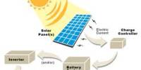
Rapid economic growth and population growth in the 20th and 21st centuries involves rapid increase in demand for energy. On the other hand, fossil fuels heavily lead to the carbon dioxide emission and their exhaustion will increasingly pose a severe problem to human life. Nuclear energy also has a serious problem in disposal of nuclear fuel wastes and nuclear accidents although it is Cox and NOx emission-free. Sustainable energy resources such as solar energy, wind energy, hydro-energy, biomass energy etc. have therefore been a focus of constant attention as alternatives to fossil fuels. They however have a disadvantage for a stable supply of energy because the amount of their energy varies seasonally, or daily, or even momentarily. A Solar Power Station/Satellite (SPS) [26] is expected to become one of the sustainable energy sources for the next generation. A conceptual image of a SPS is shown in Fig.4.1 The SPS is launched into space and it generates an enormous electric power by solar cells. The electric power is converted into microwave power in the transmitting system, and the microwave power is transmitted from the transmitting system to the receiving site on the Earth. The received microwave power is converted into commercial power. The SPS is clean and exhaustless since it is a power station whose resource is solar energy. Furthermore, the SPS supplies a stable electric power almost all through the year except that it is eclipsed by the Earth, because the power generated in space, in other words, there is no seasonal and daily variation by clouds, rain, and nights. One of the most important technologies for realization of a SPS is Wireless Power Transmission (WPT) [24, 25] from space to the Earth. A WPT system is mainly divided into three sections, as shown in Fig.4.2 a transmitting section, a receiving section and a beam forming section. The transmitting section consists of DC-RF converters and transmitting antennas. The DC-RF converters mainly include electric tubes such as magnetrons, klystrons, TWTs etc., or solid state devices. The receiving section consists of receiving antennas and RF-DC rectifiers, called “rectennas”.
The beam forming section is the intermediate section between the transmitting section and the receiving section. In order to prevent the power dissipation through the beam forming section, the transmitting section usually involves a high-gain transmitting antenna or a phased array system.
4.2 A conceptual diagram of WPT

Fig.4.2. A conceptual diagram of Wireless Power Transmission (WPT)
The objective of the present study is to develop high-efficiency and low-noise WPT. A SPS requires high overall WPT efficiency, and a high-efficiency WPT system also contributes to cost reduction and lightness in weight of the SPS from the viewpoint of thermal management. Low-noise WPT is also important since a SPS is necessary to ensure electromagnetic compatibility (EMC) with other radio applications. Our recent research activities on the WPT transmitting systems are introduced in this paper.
4.3 WPT TRANSMITTING SYSTEMS
In our research group, a magnetron, which is well-known as a microwave heating source in a microwave oven, is used for a microwave power source of a WPT system, because its DC-RF conversion efficiency is higher, it costs less, and it has smaller weight/power ratio than solid state devices. However, a magnetron has a wide oscillation bandwidth and it generates spurious noises in various frequency bands. Thus, we have been studying on a low-noise transmitting system with a magnetron.
4.4 Magnetron noise reduction
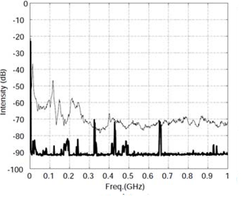
Drawbacks of a free-running magnetron are its wideband oscillation and spurious noise generation in various frequency bands. The wideband oscillation will lead to great fluctuation of a microwave beam from a WPT transmitting system, because of degradation of its frequency and phase stability. The spurious noise will interfere in the other communication systems when it is radiated from the WPT transmitting system. Therefore, narrowband oscillation and spurious noise reduction of a magnetron are essential for a low noise WPT system. With regard to the narrowband oscillation, Brown mentioned that the “internal feedback mechanism” [26] contributed to a quiet magnetron operation. The internal feedback mechanism most effectively takes place by turning off the filament current during the oscillation. Additionally, we found that the narrowband oscillation and the spurious noise reduction were effectively realized when a magnetron was operated by a dc stabilized power supply and the filament current was turned off during the operation [30]. Our experimental results showed that this operating method worked well in reducing sideband noise up to 60dB as well as the narrowband oscillation, shown in Fig.4.3 (a), spurious noise up to 50dB in high frequency bands (4GHz~10GHz), shown in Fig.4.3 (b), and line conductive noise up to 40dB in low frequency bands (~1GHz), shown in Fig.4.3 (c), although the method resulted in some degradation of dc-RF efficiency.
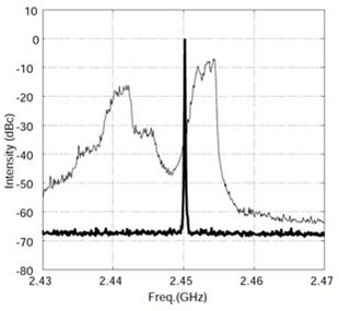
(a) Fundamental bands (2.43GHz~2.47GHz)
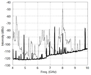
(b) Spurious noise (4GHz~10GHz)
4.5 Phase-controlled magnetron
The operating method for the magnetron noise reduction also contributes to development of a phase-controlled magnetron (PCM). The PCM is basically implemented in a phase locking of a magnetron in a phase of a reference signal. Our developed PCM consists of an injection locking method and an anode current control system with phase-locked loop (PLL) [27], in order to realize both the frequency locking and the phase locking. First, the reference signal is injected into a magnetron. Then, the anode current control system automatically locks frequency and phase of the magnetron to those of the reference signal. Owing to the accomplishment of the PCM, the experimental equipments with a phased array using PCMs at 2.45GHz and 5.8GHz, which are named SPORTS (Space Power Radio Transmission System)2.45 and SPORTS5.8 respectively, were developed [28]. The SPORTS 2.45, shown in Fig.4.4, has 12 PCMs, and each PCM has a 5-bit phase shifter. The total microwave output is about 3.6kW. There are two choices for the transmitting antenna section. One is the 4 by 3 horn antenna array. The horn antenna array system has low energy loss, but a broad beam pattern. The other is the 96 dipole antenna array with additional 2-bit phase shifter. Then microwave power from a PCM is divided into 8 and connected to 8 dipole antennas. Each dipole antenna has a 2-bit phase shifter to get the microwave beam focused more precisely. The dipole antenna system has a sharp beam pattern but large energy loss. The rectenna array receives and converts microwave power to dc. The SPORTS 5.8, shown in Fig.4.5, has a choice of two transmitting systems. One consists of 9 PCMs and 288 antenna elements. Its total microwave output is more than 1.26kW. The other consists of a solid-state amplifier and 144 antenna elements. Its microwave output is more than 7.2W. Although the solid-state amplifier system has low efficiency and low microwave output, it can control microwave beam with high resolution.
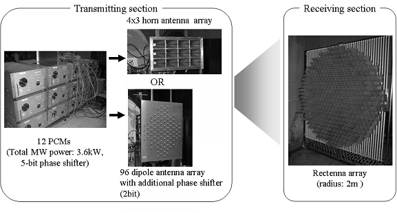
Fig.4.4 SPORTS 2.45
A light microwave power transmitter at 5.8GHz named COMET (COmpact Microwave Energy Transmitter), shown in Fig.4.6 was also developed by our research group [7]. The size of the COMET is 310mm in diameter and 99mm in thickness. It provides 270W microwave output and its weight is 7kg. So the weight per power ratio is less than 26g/W.
Moreover, we succeeded to develop a Phase-and-Amplitude-Controlled Magnetron (PACM) by tuning both the anode current and the external magnetic field simultaneously [29, 30].
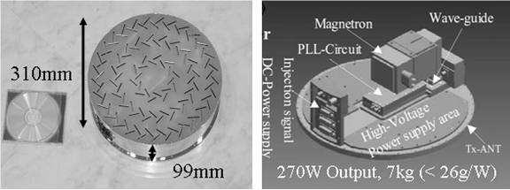
Fig.4. 6 COMET
4.6 5.8GHz CW magnetron
5.8GHz CW magnetrons, shown in Fig4.7, were developed by Panasonic Semiconductor Discrete Devices Co. Ltd. in 2000. The development of 5.8GHz CW magnetrons contributes to reduction in size and weight of the SPS transmitting system, compared to the conventional 2.45GHz magnetron. Our research group experimentally measured and evaluated fundamental performance of the 5.8GHz magnetrons, such as DC-RF conversion efficiency, a curve of anode current vs. free-running frequency, a Q value, etc.
From experimental results, DC-RF conversion efficiency of 5.8GHz CW magnetrons was measured to be about 40%; on the contrary, 2.45GHz cooker-type magnetrons have around 70% DC-RF conversion efficiency, when a magnetron is operated by a DC stabilized power supply. The Q value of 5.8GHz magnetrons degraded more than 10 times compared to that of 2.45GHz magnetrons. The results come from overheat of the cathode filament due to excessive back bombardment energy. The back bombardment energy in 5.8GHz CW magnetrons was estimated to be generated twice more than that in cooker-type 2.45GHz magnetrons.
This chapter describes the SPS interaction with space and the atmosphere, compatibility with communications and radio astronomy, and influence of the SPS and MPT on human health and bio-effects. To assure environmental safety and health, the proposed limit of the maximum power at the center of the microwave transmission beam should be controlled by tightly tuned phased-array techniques and by automatic beam defocusing.
5.1 Interaction with space and the atmosphere
5.1.1 Atmospheric effects
Very few groups have worked on possible effects of microwaves on the atmosphere. Studies presently available refer to potential effects via heating of the ionospheric electrons or via ionization of the air. Observations of transient luminous events (sprites, blue jets, elves, …) in the upper atmosphere set basic questions on the electrical processes that develop in the Earth environment. It is clear that new studies are needed on all phenomena that may influence the atmospheric electrical conductivity and thus the global electric circuit. Heating of the ionospheric electron population may affect the ionospheric plasma and the atmosphere in different ways (see section 5.1.2). The effects are probably more important between 100 and 250 km where the main chemical process controlling the ionospheric plasma concentration is the electronic recombination of O2 + and NO+. They obviously depend on the level of enhancement in the electron temperature. Of the average year (Rec. ITU-R P.837-4). [38] The rain attenuation can be calculated based on ITU-R PN618.[36] In case of Tokyo, the specific attenuation γR = 0.2dB at 5.8GHz since its rain rate is 50mm/h for 0.01% of the time (about 52.5 minutes per year). Rain rates for a part of Europe are shown in Fig. 5.1.1. Since the effective path length Le = 4.5km, the value of attenuation A=0.9 dB (81%). However, γR = 0.1dB and A= 0.45 dB (90%) at 5 GHz. These values are smaller in Europe due to less rain as shown in the figure. The microwave SPS beam is scattered by rainor hail. [35] for a rain rate, R = 50 (mm/hour), frequency of 2.45 GHz, and the elevation angle of 47 degrees, the attenuation is about 0.015 dB/km. Furthermore, the maximum interference intensity P (W) received by an antenna for terrestrial radio relay links near the rectenna site for a power density of 23 mW/cm2 is P = 6.7×10⁻¹¹R1.4h, where h (m) is the scatterer length. If R = 50~150 mm/hour and h = 3~10 km, then P = 0.1~1 mw. This level, however, would not cause nonlinear problems and interference can be removed by filters. Batanov et al[4] studied the effects of powerful microwaves on the atmosphere have been studied both theoretically and experimentally. Of particular interest are the experimental studies devoted to cleaning the troposphere of ozone. The idea involves artificially ionizing the air using high power electromagnetic waves. The necessary threshold field strength and intensity are 680 kV/m and 6 x 10⁴ W/cm2 at 15 km, corresponding to a 6 GHz continuous wave. Since microwave pulses are used for the excitation of discharges, this breakdown electric field level can be several times higher. Although both levels are much higher than the values that will be achieved from the SPS, one sees that microwave radiation may have positive effects on the Earth environment. We also need to study and monitor potential negative consequences.
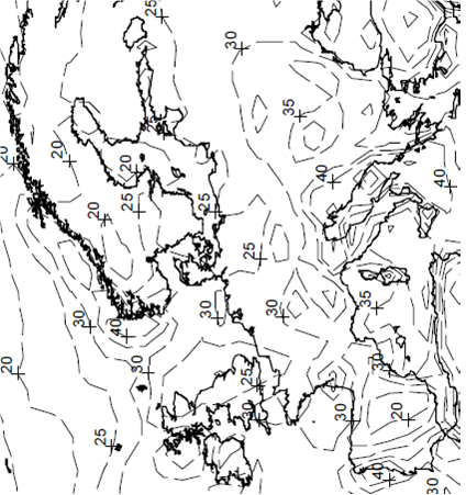
Fig.5.1.1. Rain rate (mm/h) exceeded for 0.01%
5.1.2 Ionospheric effects
Although much more published works are available, there are no conclusive observations or propagation models to provide a definitive view about the effects of microwave radiations on the ionosphere.
(1) Ohmic heating
The first obvious effect of high power microwaves on the ionosphere is resistive or Ohmic heating. The absorption of the radio waves can be calculated from the electron density and electron-neutral collision frequency profile. The effect is largest in the lower ionosphere (D and E regions) where the collision frequency is highest. Although the effect is expected to be small with increasing frequency, it could still be significant. Several authors [5] have calculated the heating effect of 3 GHz waves. They estimate that, for a power density of about 16 mW/cm2, the electron temperature could increase from about 200 K in the E region to about 1000 K. A temperature increase would result in a decrease of electron density because of a decrease in the temperature-dependent recombination rate of O2+ and NO2+. In the D region an increase in the attachment rate to O2+ also reduces electron density. To our knowledge no measurements of electron heating from high power microwaves in the ionosphere exist. The reason is probably two-fold: the difficulty of measuring electron temperatures on short time scales in the D region, and the lack of microwave heating experiments. Even if VHF and UHF radars of sufficient power-aperture produce heating effects, it is difficult to use them as both heating and measuring devices. It should also be noted that the heating effects may not be well represented by Maxwellian electron distribution function analysis[39] that is often assumed in analysis of incoherent scatter radar data, so that standard analysis techniques may not be applicable. Microwave injections from a rocket have been tried [35] (and presented in a poster review8), but Ohmic heating effects could not be observed. The lack of measured microwave heating in the ionosphere should not caste doubt on the reality of Ohmic heating caused by powerful microwaves, but only points out the shortcomings of the attempts made so far to measure it. On this rocket flight, the expected heating effect was less than 100K, which was below the detection limit of the Langmuir probe. However, the illuminated plasma volume was very small. [40] because the ionospheric heating efficiency varies as the inverse square of the radio frequency, heating effects equivalent to those from high-power microwaves can be achieved at much lower powers by heating at a lower frequency. This is done using ionospheric modification or heating facilities that are simply high-power (~1MW) short-wave (2 to 10 MHz) transmitters radiating upwards using high gain (16 to 30 dB) antenna arrays. D-region Ohmic heating effects are clearly observable indirectly through the conductivity and current modulation experiments9 and the sometimes dramatic heating effects on polar mesospheric summer radar echoes. [31, 32] direct measurements of the temperature enhancement using incoherent scatter radar are, however, difficult and rate. [33]
(2) Self-focusing effects
Thermal self-focusing takes place as a result of a positive feedback loop. Small natural density fluctuations give rise to a spatial variation in the refractive index, resulting in slight focusing and defocusing of the microwave. This slight differential heating of the ionospheric plasma results in a temperature gradient driving the plasma from the focused region and thereby amplifying the initial perturbation. Such effects are well known and have been studied from HF-heating experiments, but it is unclear how important this is for an under dense plasma where the microwave frequency is much greater than the plasma frequency.
(3) Three-wave interactions
The heating effects discussed above are the result of non-resonant interactions with the plasma. Another effect of high power microwaves is the production of plasma waves through resonant interactions, in particular through parametric instabilities. There have been several theoretical predictions that microwaves at high power may produce instabilities in the ionosphere. Matsumoto [44] and Matsumoto et al. [30] demonstrated that the microwaves may decay into forward-traveling electron plasma waves (Raman scattering) or ion acoustic waves (Brillouin scattering) and a backward-traveling secondary microwave. The electron plasma waves could be Langmuir waves when the excitation is parallel to the geomagnetic field, or electron cyclotron waves for excitation perpendicular to the field. Dysthe et al.[45] and Cerisier et al.[38] examined the case of two powerful microwaves having a frequency difference equal to the local ionospheric plasma frequency, typically 2 to 10 MHz. The ponder motive force, which is proportional to the product of the two electric fields, can be strong enough to excite a parametric instability that results in Langmuir waves being produced. One result of a ground-based radar experiment near 1 GHz16 shows that such effects may indeed take place in the ionosphere. The three-wave interactions are expected to be most effective in the F region, above about 170 km. Apart from the radar experiment of Lavergnat et al.[36] there is, to our knowledge, only one other report of plasma waves being caused in the ionosphere by powerful microwave transmissions. This was from a 830W, 2.45 GHz transmitter on a mother-daughter Japanese rocket experiment (MINIX) where electrostatic electron-cyclotron waves at 3/2 the local electron gyro frequency and electron plasma waves above the local plasma frequency were observed[48,40] and presented in a poster review.[49] It was found that the excited waves differed from the initial theoretical expectations18 in that the line spectrum expected from a simple three-wave coupling theory was in fact a broad spectrum, and the electron cyclotron harmonics were stronger than the Langmuir waves. Both these features could be successfully modeled using a more realistic computer simulation [39] where the nonlinear feedback processes were fully incorporated. From these simulation results, it was estimated that 0.01 percent of the microwave beam energy from the SPS would be converted to electrostatic waves. In conclusion, there have not been enough experiments with powerful microwaves in the ionosphere to determine with confidence the importance of instabilities as a loss mechanism for the beam and as a source of plasma waves and heating of the ionosphere. In the neighborhood of the satellite the power density will be high and its effects on the ionosphere will be examined experimentally. Care must be taken in the choice of frequency separations if multiple frequencies are used to beam down the power. Effects on the atmosphere are not expected.
5.1.3 Effects of electric propulsion on the magnetosphere
In the process of SPS construction, large high-power electric propulsion systems are needed. The electric propulsion systems inject heavy ions accelerated by electrodes powered by the photovoltaic cells. For transformation of orbits around the equator, the heavy ions are injected perpendicular to the Earth’s magnetic field. The injection can strongly disturb the electromagnetic environment surrounding the ion engine in the plasma sphere and the magnetosphere through interaction between the heavy-ion beam and the magnetosheric plasmas. The interaction between the heavy-ion beam and the magnetic field has been studied theoretically.[ 50 , 51] Based on an MHD analysis, Chiu[51] predicted that Argon ion injection could excite Alfven waves propagating along the magnetic field down to the ionosphere and being reflected back. He also predicted that injected Argon ions can accumulate in the magnetosphere, significantly changing the plasma environment. Curtis and Grebowsky[49] showed that the bulk of the injected ion beam is not stopped in the magnetosphere. However, the relatively small fraction of the beam that is not stopped may give rise to a large distortion in the magnetospheric plasma population. They also evaluated possible loss mechanisms from the magnetosphere for this artificial ion component. The interaction of the heavy ions and the surrounding magnetized plasma field has been studied by particle simulations using hybrid code, where motions of ions are solved as particles while electrons are treated as a neutralizing fluid. As an initial response to the injection, a shock structure can be formed in the ambient plasma along with generation of magneto-hydro-magnetic waves and associated heating of the background plasmas.[48] It has to be noted that heating processes and parametric instabilities may also take place within the plasma sphere, in the neighborhood of the satellite. The plasma is less dense but there is a high level of wave activity. The artificial generation or loss of extremely low (ELF) and ultra low (ULF) frequency waves in that region may have consequences on the dynamics of the radiation belts.
5.2 Compatibility with other radio services and applications
Undesired emissions, such as grating lobes, sidelobes, carrier noise, harmonics, spurious, and out-of-band emissions of any Space Solar Power System must be suppressed sufficiently to avoid interference with other radio services and applications, in accordance with the provisions of the ITU-R Radio Regulations (RR). This applies not only to any eventual full power operational systems, but also to all developmental, test and intermediate power prototype systems, both in space and on the ground. Hence this is a near term issue, even though it may take decades before full systems become operational.
Most SPS microwave systems are assumed to use frequency bands around 2.5 GHz or 5.8 GHz. These are allocated in the ITU-R Radio Regulations to a number of radio services and are also designated for Industry, Science and Medical (ISM) applications. The ITU Radio Regulations define ISM applications as follows. RR 1.15 Industrial, scientific and medical (ISM) applications (of radio frequency energy): Operation of equipment or appliances designed to generate and use locally radio frequency energy for industrial, scientific, medical, domestic or similar purposes, excluding applications in the field of telecommunications. Note that as presently defined the ISM bands are for local use only. The following Radio Regulations govern the use of the ISM applications. RR 5.150 The following bands: 13,553-13,567 kHz, 26,957-27,283 kHz, 40.66-40.70 MHz, 902-928 MHz in Region 2, 2,400-2,500 MHz, 5,725-5,875 MHz, and 24-24.25 GHz are also designated for industrial, scientific and medical (ISM) applications. Radiocommunication services operating within these bands must accept harmful interference which may be caused by these applications. ISM equipment operating in these bands is subject to the provisions of No. 15.13. RR 15.13 Administrations shall take all practicable and necessary steps to ensure that radiation from equipment used for industrial, scientific and medical applications is minimal and that, outside the bands designated for use by this equipment, radiation from such equipment is at a level that does not cause harmful interference to a radiocommunication service and, in particular, to a radio navigation or any other safety service operating in accordance with the provisions of these Regulations.
The intended bandwidth of SPS emissions is quite narrow, as an essentially monochromatic wave without modulation will be used. As noted in Section 5.1.2, care must be taken in the choice of frequency separations if multiple frequencies are used to beam down the power.
5.2.1 Compatibility with other services such as Radio Astronomy
An interference assessment on mainly 2.45 GHz was published in IEEE Microwave Magazine. [47] The following is a partial list of mechanisms by which an SPS could cause interference. [46]
1) The power transmission signal, its harmonics, and any sidebands that might be present in the fundamental frequency reference, which will appear coherently at all power amplifiers of the system.
2) Noise generated in the power output stages. This will not be coherent at individual power amplifiers and so will not be beamed like the power signal but spread much more widely in angle. The spectrum might only be a few tens of MHz wide if the transmitter elements are highly tuned (e.g. klystrons) and could be broader for solid-state devices.
3) Thermal noise emitted by the solar collector arrays. This may represent a significant
broadband component of radiated power in the microwave spectrum.
4) Reflection by the collector arrays of high-powered transmitters in space or on the ground. This can occur over a wide range of frequencies.
5) Spurious emission at unwanted frequencies or in unwanted directions from the power
transmitters associated with component failure of the amplifiers themselves or of parts of the antenna system. It is not certain whether failing transmitters might become unlocked in frequency, generate spurious modes or just die quietly.
6) Harmonics and noise generated in the rectenna.
7) Inter modulation between the power signal and other radio signals generated in a rectenna or in nonlinear elements in the high field areas near a rectenna. Carrier noise, harmonics, and spurious emissions of the WPT signal must be quite small to avoid interference with other radio services in operation around the world. Grating lobes and sidelobes of the WPT beam should be low enough to make the affected region as small as possible. Also, grating lobes should be mitigated because they are a direct loss of transmitter power. It is important that compatibility be evaluated for full systems, not just single units. Many units of 1 GW will be required if satellite solar power is to represent a significant contribution to future energy needs. The 2.45 and 5.8 GHz ISM bands share a common frequency allocation worldwide. Familiar applications include radio controllers, microwave ovens, RF-ID (radio tags) and drying of cut lumber. To date they have been used for WPT applications for demonstration and experimental purposes.25 The 2.45 GHz ISM band (2400-2500MHz) and the 5.8 GHz ISM band (5725-5875 MHz), however, have already been allocated to various other services as well. Recently, the 2.45 GHz ISM band has been widely used for Radio LAN (IEEE 802.11b and g) applications. The frequency allocation of the 2.45 GHz Radio LANs occupies almost the whole band. The 5.8 GHz ISM band is also heavily used for various applications. The 5725-5850 MHz band is allocated to the Radiolocation service. DSRC (Dedicated Short-Range Communications), described in Recommendation ITU-R M.1543, is also expected to use the band. The 5850-5925 MHz band is allocated to Fixed/Mobile services and is used for terrestrial Electronic News Gathering (ENG) in some countries. The second, the sixth, ninth and 20th harmonics of the 2.45 GHz ISM band overlap with radio astronomy bands (4.9-5.0, 22.1-22.5 and 48.96-49.06 GHz). It is expected that the interference level near 4.9 GHz would be very much higher (40 dB or more, depending on the system) than the harmful interference threshold. Hence the upper half, 2.45-2.5 GHz, cannot be used for SSPS. The harmonic situation is better for the 5.8 GHz band. However, many harmonics of the 2.45 GHz and the 5.8 GHz band overlap the 76 – 116 GHz radio astronomy band. The spurious and out-of-band (OOB) emission from high-power\ transmitters is likely to interfere with adjacent radio astronomy bands. Frequency allocation for SPS must avoid harmful interference with radio astronomy applications, which use very sensitive passive receivers. Spurious emissions must be suppressed sufficiently to protect the Radio Astronomy Service, and rectennas must be located far from radio astronomy observing sites. As radio astronomy is fully passive and celestial objects have no lower limit in intensity of emission, its observing systems have been advanced to become extremely sensitive.
5.2.2 Reflection and Thermal Emission from Solar Cells [45, 47]
In the radio region, solar cells reflect solar radio emission in a continuous frequency region of 100 MHz through 100GHz and beyond. The power flux densities are 0.1 – 1 M×10-26 W/m2 /Hz (quiet Sun) and 100 – 1000 M×10-26 W/m2 /Hz (burst). These values are six to ten orders of magnitude higher than those from typical cosmic radio sources. This means that radio astronomical observations may be affected by these reflections, depending on the telescope location on the Earth. The apparent angular size of the solar cell array with a diameter of about 13 km is close to 1 arcminute, which is 1/30 of those of the Sun and the Moon, and a little larger than Jupiter (about 40 arc seconds), the largest planet of the solar system. Because the SPS systems are always seen at the same locations, they would prevent astronomical observations of those regions of the sky. Even the JAXA 2002 Model, for example, whose diameter of the primary mirror is about 3km (about 15 arc seconds in angular diameter), would obscure many celestial objects forever. This model system does not represent a large addition to the terrestrial power capability. The effect grows as multiple such systems are added to make an operational system. Optical and infrared astronomy will suffer from reflection by the solar cells. This was studied extensively for the earlier US system. The National Research Council panel concluded: 27 “The diffuse night-sky brightness produced by the reference SPS would interfere seriously with optical astronomical measurements from the Earth. This interference would be concentrated in an area on either side of the satellite arc and would prevent the measurement of weak astronomical objects in those areas.” An important effect of the SPS on radio astronomy arises from the passive thermal radiation of the solar cells. There will be zones centered on the geostationary orbit in which observations over a wide range of frequencies will be precluded, not just at harmonics of the power transmission. For example, in the studies of the US reference system proposed in 1978, the thermal radiation from the collectors of one satellite were estimated to produce a level about 10 dB below the detrimental threshold levels of Recommendation ITU-R RA.769 assuming a unity gain antenna over a wide range of frequencies. The interference is detrimental if one points a radio telescope so that receiving sidelobes above 10 dBi lie on the orbit. For 32-25log(φ) sidelobes, that means pointing closer than about ±7.5 degrees to the orbit. There will also be noise generated in the transmitting tubes or power transistors, which could be rather wide in bandwidth if these power amplifiers are not narrow-band devices. This could be stronger than the thermal noise, but will depend on the characteristics of the particular devices used. With a full system of satellites in orbit, satellites would be distributed fairly continuously around the GEO, so that at any radio or optical observatory a band of sky centered on the orbit would be permanently blocked from certain observations at essentially all frequencies. The substantial loss of observable sky resulting from such wideband noise emission would be severely harmful. Such effects are, however, expected to be smaller. For example, in the case of the JAXA 2003 model, the reflected light by the huge mirror is specific and directed to the solar cell panels and the light reflected by the cells is directed perpendicular to the direction of the Earth.
5.3 MPT on Human health and bio-effects
The concept of solar-power satellites (SPS) and wireless-power transmission (WPT)envisions the generation of electric power by solar energy in space for use on Earth.[28,29] The system would involve placing a constellation of solar power satellites in geostationary Earth orbits. Each satellite would provide between 1 and 6 GW of power to the ground, using a 2.45 or 5.8-GHz microwave beam. The power-receiving rectenna on the ground would be a structure measuring 1.0 to 3.4 km in diameter. The higher (5.8 GHz) frequency has been proposed since it has a similar atmospheric transparency. Although, in principle, the higher frequency could involve a reduced size for the transmitting and receiving antennas, it can be seen from the table that current designs have opted for larger transmitting antennas and smaller rectenna sites, but a larger power density on the ground to conserve land use, especially in Japan. A joint effort between the Department of Energy (DOE) and the National Aerospace Administration (NASA) in the US extensively investigated the feasibility of SPS-WPT during 1976-1980. The effort generated a Reference System Concept for Solar Power Satellites. The DOE–NASA Reference System involved placing a constellation of solar power satellites (5 x 10 x 0.5 km deep) in geostationary Earth orbits, each of which would provide 5-GW of power to major cities on the ground, using a 2.45-GHz microwave beam. The Reference System’s sixty satellites were contemplated to deliver a total of 300 GW of generating capacity. The transmitting antenna was about 1 km in diameter. The power-receiving rectenna on the ground was a 10 x 13-km structure. Japan’s Ministry of Economy, Trade and Industry (METI) had announced plans to launch research for a solar-power-generation satellite and to begin operating a giant solar-power station by 2040. This program is expected to design and operate an SPS-WPT system that would ensure the microwaves would not interrupt cellular mobile telephone and other wireless telecommunications services. The Japan Aerospace Exploration Agency (JAXA) has proposed and evaluated various system configurations for operation at 5.8 GHz. For example, the JAXA2 model would have a maximum power density of 100 mW/cm2 (1000 W/m2) on the ground. A smaller transmitting system would have a density of 26 mW/cm2 (260 W/m2) at the rectenna site on the ground. A variety of environmental considerations and safety-related factors continue to receive consideration, albeit at a low priority level. The biological effects and health implications of microwave radiation have been a subject of study for many years.[30,31,32] In fact, the cumulative data have allowed the establishment of recommendations for safety levels for humans under a variety of exposure conditions. For example, the ICNIRP (and Japanese) guideline is 5 or 1 mW/cm2 for occupationally exposed vs. the general public, at either 2.45 or 5.8 GHz.33 The corresponding limits for IEEE standards for maximum permissible human exposure to microwave radiation, at 2.45 or 5.8 GHz, are 8.16 or 10 mW/cm2 averaged over six min, and 1.63 or 3.87 mW/cm2 averaged over 30 min, respectively, for controlled and uncontrolled environments.34 The controlled and uncontrolled situations are distinguished by whether the exposure takes place with or without knowledge of the exposed individual, and is normally interpreted to mean individuals who are occupationally exposed to the microwave radiation, as contrasted with the general public. As can be seen from the Table, the proposed power densities range from 23 to 180 mW/cm2 above the rectenna at the center of the microwave beam, where power densities would be maximum. At 2.45 GHz, the power density is projected to be 1 mW/cm2 at the perimeter of the rectenna. Beyond the perimeter of the rectenna or 15 km, the side lobe peaks would be less than 0.01 mW/cm2. Clearly, beyond the perimeter of the rectenna, the potential exposure would be well below that currently permissible for the general public. The danger of loss of control of highly focused beams may be minimized by tightly tuned phased-array techniques and by automatic beam defocusing to disperse the power if loss of contril occurs. Defocusing would degrade the beam toward a more isotropic radiation pattern, which would give rise to even lower power density on the ground. [51] Near the center of the microwave beam, power densities would be greater than the permissible level of exposure for controlled situations. Except for maintenance personnel, human exposure would normally not be allowed at this location. In the case of occupationally required presence, protective measures, such as glasses, gloves and garments could be used to reduce the exposure to a permissible level.
However, at 25 mW/cm2, research has shown that some birds exhibit evidence of detecting the microwave radiation. This suggests that migratory birds, flying above the rectenna, might suffer disruption of their flying paths. Moreover, at higher ambient temperatures, larger birds tend to experience more heat stress than smaller ones, during 30 min of exposure. [49] This result is consistent with the knowledge that the larger birds, having a larger body mass, absorb a relatively greater quantity of microwave radiation than do the smaller birds. The additional heat, from microwave energy deposited inside the body, could be stressing the thermal regulatory capacity of the larger birds. Thus to assure environmental health and safety, the proposed limit for the “center-of-beam” power densities is approximately 25 mW/cm2 for microwave transmission. Note that the average absorption remains fairly stable for frequencies above 2 GHz,30, 37 except when the frequency becomes much higher, i.e., 10 GHz, where the skin effect takes over, the maximum tolerable exposure at 5.8 GHz would be essentially the same as for 2.45 GHz. We have to discuss the microwave (over GHz) effect on human health imposed by the SPS system. There is a long history concerning the safety of microwave energy.38 Contemporary RF/microwave standards are based on the results of critical evaluations and interpretations of the relevant scientific literature. The specific absorption rate (SAR) threshold for the most sensitive effect considered potentially harmful to humans, regardless of the nature of the interaction mechanism, is used as the basis of the standard. The SAR is only related to a heating problem, which is regarded as the only microwave effect on human health. Discussions about the maximum microwave power density inside the rectenna site are necessary. The maximum power density depends on the antenna size and the frequency, which directly affect the total cost. In the present JAXA2 model, the microwave power density is 100 mW/cm2 at the center of the rectenna site, which is above the safe level. This area should be strictly controlled. Outside of the rectenna area, the intensities are kept below the safe level. A possible change of the safe level in the future could cause changes of the SPS design.
6.1 Comparison with fossil fuels
The relatively low price of energy today is entirely dominated by the historically low cost of carbon based fossil fuels (e.g., petroleum, coal and natural gas).
There are several problems with existing energy delivery systems. They are subject to (among other problems) political instability for various reasons in various locations — so that there are large hidden costs in maintaining military or other presence so as to continue supplies depletion (some well regarded estimates suggest that oil and gas reserves have been in net decline for some time and that price increases and supply decreases are inevitable) oil prices rose from around $20/bbl in the early 2000s to over $130/bbl in early 2008, despite no major disruptions in supply, suggesting to some industry observers (e.g., Matthew Simmons) that the days of cheap oil are over greenhouse pollution — fossil fuel combustion emits enormous quantities of carbon dioxide (CO2), a greenhouse gas, contributing to global warming and climate change[44]. Following the Kyoto Treaty, 141 countries introduced the first system of mandatory emissions control via carbon credits. The ultimate direction of such policies is to increase efficiency of fossil fuel use, perhaps to the point of elimination in some countries or even globally. But, the energy requirements of Third World or developing countries (e.g., China and India) are increasing steadily. Because of the net increase in demand, energy prices will continue to increase, though how fast and how high are less easily predicted.
6.2 Comparison with nuclear power (fission)
Detailed analyses of the problems with nuclear power specifically (nuclear fission) are published elsewhere[43]. Some are given below, with some comparative comments:
- nuclear proliferation — not a problem with SPS
- disposal and storage of radioactive waste — not a problem with SPS
- preventing fissile material from being obtained by terrorists or their sponsors — not a problem with SPS
- public perception of danger — problem with both SPS and nuclear power
- consequences of major accident, e.g., Chernobyl — effectively zero with SPS, save on launch (during construction or for maintenance)
- military and police cost of protecting the public and loss of democratic freedoms — control of SPS would be a power/influence center, perhaps sufficient to translate into political power. However, this has not yet happened in the developed world with nuclear power.
- installation delays. These have been notoriously long with nuclear power plants (at least in the US), and may be reduced with SPS. With sufficient commitment from SPS backers, the difference may be substantial.
On balance, SPS avoids nearly all of the problems with current nuclear power schemes, and does not have larger problems in any respect, although public perception of microwave power transfer (i.e. in the beams produced by an SPS and received on Earth) dangers could become an issue.
6.3 Comparison with nuclear fusion
Nuclear fusion is a process used in stars, thermonuclear bombs (e.g., the H-bomb), and in a very small way some laboratory experiments. Projected nuclear fusion power plants would not be explosive, and will likely be inherently failsafe as the conditions for fusion on Earth are extremely hard to maintain and the reaction will promptly stop if any of them is changed (eg, via component or control system maladjustment or failure). However, sustained nuclear fusion generators have only just been demonstrated experimentally, despite extensive research over a period of several decades (since approximately 1952. There is still no credible estimate of how long it will be before a nuclear fusion reactor could become commercially possible; fusion research continues on a significant scale, including an internationally supported large scale project — the facility currently under construction has been funded at about €10 billion.There has been much criticism of the value of continued funding of fusion research given the continued failure to produce even small amount of net power in any of the varied attempted schemes. Nevertheless, proponents have successfully argued in favor of ITER funding
In contrast, SPS does not require any fundamental engineering breakthroughs, has already been extensively reviewed from an engineering feasibility perspective over some decades, and needs only incremental improvements of existing technology to be deployable. Despite these advantages, SPS has received minimal research funding to date in comparison.
6.4 Comparison with terrestrial photovoltaic solar power
Per-kilowatt-hour photovoltaic costs have been in exponential decline for decades, with a 20-fold decrease from 1975 to 2001. Let us consider a ground-based solar power system versus an SPS generating an equivalent amount of power. An SPS requires much less ground area per kilowatt (approx 1/5th), depending on the location of the ground-based system. A ground-based system intercepts an absolute maximum of only one third of the solar energy an array of equal size could intercept in space, since no power is generated at night and less light strikes the panels when the Sun is low in the sky or weather interferes. The rectenna of an SPS would have a smaller footprint than the equivalent solar array, as it receives more power per unit area. A solar panel in the contiguous United States on average delivers 19 to 56 W/m² An SPS rectenna would deliver about 23mW/cm² (230 W/m²) continuously, hence the size of rectenna required per collected watt would be about 8.2% to 24% that of a terrestrial solar panel. A ground-based solar array is considerably cheaper to construct. A ground-based solar array requires no new technology. An SPS rectenna can be made transparent and thus would not impact land use. For example, crops could be grown beneath it. An SPS provides continuous power, whilst a ground-based system would require some form of energy storage if it were to provide power at night. Ground-based systems are more vulnerable to terrorist attack. A ground based system requires continual maintenance. Wear and tear on orbital installations can be reduced by care in design and fabrication. An SPS can deliver power where needed by redirecting its microwave beam, whilst a ground-based system must rely on the grid to distribute its power. However ground-base systems may be deployed in a distributed manner (say to rooftops). Both SPS and ground-based solar power could be used to produce chemical fuels for transportation and storage, as in the proposed hydrogen economy. Or they could both be used to run an energy storage scheme (such as pumping water uphill at a hydropower generation station). Advances in solar cell efficiency (eg, improved construction techniques) that make an SPS more economically feasible make a ground-based system more economic as well. Also, many SPS designs assume the framework will be built with automated machinery supplied with raw materials, typicallyaluminium. Such a system could be (more or less easily) adapted for operation on Earth, no launching required. However, Earth-based construction already has access to inexpensive human labor that would not be available in space, so such construction techniques would have to be extremely competitive to be significant on Earth.
6.4.1 Solar panel mass production
Currently the costs of solar panels are too high to use them to produce bulk domestic electricity in most situations. However, mass production of the solar panels necessary to build an SPS system would be likely to reduce those costs sufficiently to change this — perhaps substantially — especially as fossil fuel costs have been increasing rapidly. But, any panel design suited to SPS use is likely to be quite different than earth suitable panels, so not all such improvements will have this effect. This may benefit earth based array designs as costs may be lower (see the cost analysis above), but will not be able to take advantage of maximum economies of scale, and so piggyback on production of Earth based panels. It should be noted, however, that there are also frequent developments in the production of solar panels. Thin film solar panels and so-called “nanosolar” might increase collection efficiency, reduce production costs as well as weight, and therefore reduce the total cost of an SPS installation. In addition, private space corporations could become interested in transporting goods (such as satellites, supplies and parts of commercial space hotels) to LEO (Low Earth orbit), since they already are developing spacecraft to transport space tourists . If they can reduce costs, this will also increase the economic feasibility of an SPS.
6.5 Comparison with other renewables (wind, tidal, hydro, geothermal)
Most renewable energy sources (for example, tidal energy, hydro-electric, geothermal, ethanol), have the capacity to supply only a tiny fraction of the global energy requirement, now or in the foreseeable future. For most, the limitation is geography as there simply are very few sites in the world where generating systems can be built, and for hydro-electric projects in particular, there are few sites still open. For 2005, in the US, hydro-electric power accounted for 6.5% of electricity generation, and other renewables 2.3%. The U.S. Govt. Energy Information Administration projects that in 2030 hydro-power will decline to 3.4% and other renewables will increase to 2.9%.
6.5.1 Comparison with biofuels
Ethanol power production depends on farming in the case of corn or sugar cane, currently the two leading sources of ethanol fuel. There is insufficient farming capacity for both significant energy production and food production. Corn prices have risen substantially in 2006 and 2007, partly as a result of nascent ethanol production demand. Due to the high energy cost of industrial agriculture as well as the azeotropic distillation necessary to refine ethanol, serious questions remain about the EROEI of ethanol from corn. Ethanol from cellulose (eg, agricultural waste or purpose collected non-cultivated plants, eg, switchgrass) is not practicable as of 2007, though pilot plants are in development. Processing improvements (eg, a breakthrough in enzyme processing) may change this relative disadvantage.
6.5.2 Comparison with wind power
Wind power is somewhat unique among the renewables as having emerged as competitive with fossil fuels on cost (similar to hydro), but unlike hydro has significant potential for expansion. Wind power has been the fastest-growing form of renewable energy throughout the 2000s, growing at an annual rate of approximately 30% . As of 2008, wind power’s share of global energy output remained small, but wind power accounted for a large share of new power generation capacity in several countries including the United States and the United Kingdom. Improvements in technology, especially the trend toward largerwind turbines mounted on taller towers, has reduced the cost of wind power to be competitive with fossil fuel. The potential for wind power appears to be very large. For example, just the four windiest states in the United States (North Dakota, Texas, Kansas, and South Dakota), have wind resources that could equal the current electricity consumption of the entire country. Offshore wind resources appear to be even larger than on-shore wind resources. One advantage ofwind farms is their ability to expand incrementally; individual wind turbines can be assembled on site at a typical rate of approximately one per week, and begin generating electricity (and thus revenue) as soon as they connect to the transmission grid. This gives wind power a lower capital risk compared to large-scale power generation schemes that require heavy investment for years before they become operational (e.g., hydroelectric power, nuclear power). Ocean-based windpower offers access to very large wind resources (there being large areas for potential installations, and winds tend to blow stronger and steadier over water than over land due to reduced surface friction), but it is strongly affected by two factors: the difficulty of long distance power transmission as many regions of high demand are not near the sea, and by the very large difficulty of coping with corrosion, contamination, and survivability problems faced by all seaborne installations. Some potential locations for offshore wind turbines suffer less from these problems, such as the Great Lakes of the United States and Canada, which are surrounded by well-developed power grids and large populations of electricity consumers. The lakes, being fresh water, would pose fewer corrosion problems, and construction in these environments is well-understood.
In Sum If we concentrate at the last chapter then we can say that the solar power satellite is the better performer than that of any sorts of power mainly from the point of cost. If we develop a satellite and launch it for gather solar cells then it is very much expensive for the first time. Wireless power transmission is also an important factor here. But it isn’t creating for the only one time. In Japan, many of their industries are using solar system which is obtained from the satellite. America and a very few number of rich countries are also using this technology. We didn’t use the solar power for the maximization. So the world’s are investigate how it would be used for the maximization. If I would get more time then my objective of the present study is to develop high-efficiency and low-noise Wireless Power Transmission.