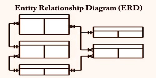
Entity Relationship Diagram, also known as ERD, ER Diagram, or ER model, is a type of structural diagram for use in database design. It is a type of flowchart that illustrates how “entities” such as people, objects, or concepts relate to each other within a system. An ERD contains different symbols and connectors that visualize two important information: The major entities within the system scope, and the inter-relationships among these entities.
ER Diagrams are most frequently wont to design or debug relational databases within the fields of software engineering, business information systems, education, and research. Also referred to as ERDs or ER Models, they use an outlined set of symbols like rectangles, diamonds, ovals, and connecting lines to depict the interconnectedness of entities, relationships, and their attributes. They mirror grammatical structure, with entities as nouns and relationships as verbs.
While ERD are mostly developed for designing relational databases in terms of concept visualization and in terms of physical database design, there are still other situations when ER diagrams can help. An ER Diagram contains entities, attributes, and relationships.
ER diagrams are associated with system diagrams (DSDs), which concentrate on the relationships of elements within entities rather than relationships between entities themselves. ER diagrams are also often used in conjunction with data flow diagrams (DFDs), which map out the flow of knowledge for processes or systems.
There are three basic elements in ER-Diagrams:
Entities are the “things” for which we want to store information. An entity is a person, place, thing or event.
Attributes are the data we want to collect for an entity.
Relationships describe the relations between the entities.
ER Diagrams are composed of entities, relationships and attributes. They also depict cardinality, which defines relationships in terms of numbers. Here’s a glossary:
Entity – An ERD entity is a definable thing or concept within a system, such as a person/role (e.g. Student), object (e.g. Invoice), concept (e.g. Profile) or event (e.g. Transaction) (note: In ERD, the term “entity” is often used instead of “table”, but they are the same). When determining entities, think of them as nouns. In ER models, an entity is shown as a rounded rectangle, with its name on top and its attributes listed in the body of the entity shape.
Entity Attributes – Also known as a column, an attribute is a property or characteristic of the entity that holds it. An attribute has a name that describes the property and a type that describes the kind of attribute it is, such as varchar for a string, and int for integer. When an ERD is drawn for physical database development, it is important to ensure the use of types that are supported by the target RDBMS.
Entity keys – Refers to an attribute that uniquely defines an entity in an entity set. Entity keys can be super, candidate, or primary.
- Super key: A set of attributes (one or more) that together define an entity in an entity set. Candidate key: A minimal super key, meaning it has the least possible number of attributes to still be a super key. An entity set may have more than one candidate key.
- Primary key: A candidate key chosen by the database designer to uniquely identify the entity set.
- Foreign key: Identifies the relationship between entities.
Relationship – How entities act upon each other or are associated with each other. Think of relationships as verbs. For example, the named student might register for a course. The two entities would be the student and the course, and the relationship depicted is the act of enrolling, connecting the two entities in that way. Relationships are typically shown as diamonds or labels directly on the connecting lines.
An ER model is typically drawn at up to three levels of abstraction:
- Conceptual ERD / Conceptual data model
- Logical ERD / Logical data model
- Physical ERD / Physical data model
While all the three levels of an ER model contain entities with attributes and relationships, they differ within the purposes they’re created for and also the audiences they’re meant to focus on. A general understanding to the three data models is that business analyst uses a conceptual and logical model to model the business objects exist within the system, while database designer or database engineer elaborates the conceptual and logical ER model to supply the physical model that presents the physical database structure ready for database creation.
Sometimes, engineers will branch out ER diagrams with additional hierarchies to add necessary information levels for database design. For example, they may add groupings by extending up with superclasses and down with subclasses.
Information Sources: