Cavity Magnetron
Definition
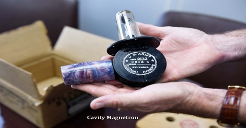
Cavity Magnetron is a high-powered vacuum tube that generates microwaves using the interaction of a stream of electrons with a magnetic field while moving past a series of open metal cavities. It is a source of microwave energy used in medical linear accelerators to accelerate electrons to the therapeutic energies.
The frequency of the microwaves produced, the resonant frequency, is determined by the cavities’ physical dimensions. Unlike other vacuum tubes such as a klystron or a traveling-wave tube (TWT), the magnetron cannot function as an amplifier in order to increase the intensity of an applied microwave signal; the magnetron serves solely as an oscillator, generating a microwave signal from direct current electricity supplied to the vacuum tube.
The cavity magnetron tube was later improved by John Randall and Harry Boot in 1940 at the University of Birmingham, England. The high power of pulses from their device made centimeter-band radar practical for the Allies of World War II, with shorter wavelength radars allowing detection of smaller objects from smaller antennas. The compact cavity magnetron tube drastically reduced the size of radar sets so that they could be more easily installed in night-fighter aircraft, anti-submarine aircraft and escort ships.
Operation of Magnetron
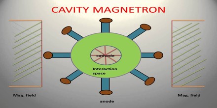
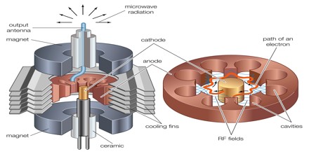
The magnetron is called a “crossed-field” device in the industry because both magnetic and electric fields are employed in its operation, and they are produced in perpendicular directions so that they cross. The applied magnetic field is constant and applied along the axis of the circular device illustrated. The power to the device is applied to the center cathode which is heated to supply energetic electrons which would, in the absence of the magnetic field, tend to move radially outward to the ring anode which surrounds it.
The axial magnetic field exerts a magnetic force on these charges which is perpendicular to their initially radial motion, and they tend to be swept around the circle. As these electrons sweep toward a point where there is excess negative charge that charge tends to be pushed back around the cavity, imparting energy to the oscillation at the natural frequency of the cavity. This driven oscillation of the charges around the cavities leads to radiation of electromagnetic waves, the output of the magnetron.
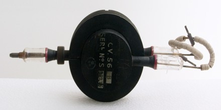
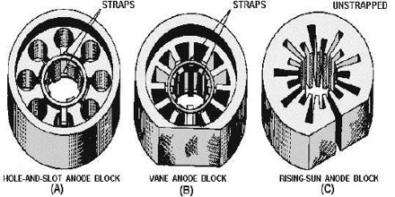
Mechanically, the cavity magnetron consists of a large cylinder of metal with a hole drilled through the center of the circular face. A wire acting as the cathode is run down the center of this hole, and the metal block itself forms the anode. Around this hole, known as the “interaction space”, are a number of similar holes drilled parallel to the interaction space, separated only a very short distance away.
Applications of Cavity Magnetron
Applications for magnetrons include radar, heating, and lighting systems.
Radar – In a radar set, the magnetron’s waveguide is connected to an antenna. The magnetron is operated with very short pulses of applied voltage, resulting in a short pulse of high power microwave energy being radiated. As in all primary radar systems, the radiation reflected off a target is analyzed to produce a radar map on a screen.
Heating – In microwave ovens, the waveguide leads to a radio frequency-transparent port into the cooking chamber. As the fixed dimensions of the chamber, and its physical closeness to the magnetron, would normally create standing wave patterns in the chamber, a motorized fan-like stirrer is placed in the waveguide to randomize the pattern. This is not always effective for larger objects in the chamber, and most modern microwave ovens also include a rotating table for the food to sit on, the turntable.
Lighting – In microwave-excited lighting systems, such as a sulfur lamp, a magnetron provides the microwave field that is passed through a waveguide to the lighting cavity containing the light-emitting substance. Although efficient, these lamps are much more complex than other methods of lighting and therefore not commonly used.
Types of Magnetrons
Cavity Magnetrons use a high-voltage DC power supply to bring a hot-filament cathode to a high negative potential. Permanent magnets located next to the filament produce a magnetic field that causes electrons to spiral outward instead of moving directly toward the anode.
Cylindrical Cavities that are spaced around the rim of the magnetron chamber induce a resonant, high-frequency field. An antenna connected to a waveguide extracts a portion of this radio frequency (RF) field, and the waveguide directs the RF energy to the load.
Circular Magnetrons carry product specifications for maximum sputtering power, cooling requirements, target, mounting style, maximum temperature, source-to-substrate distance, and materials. There are five parameters for maximum sputtering power: direct current (DC), radio frequency (RF), cathode voltage, discharge current, and operating pressure. Cooling requirements include flow rate at maximum power, maximum input temperature, and open drain. Form, diameter, thickness, and cooling method are target parameters.
Rectangular Magnetrons are well-suited for coating broad substrates and achieving very high throughputs. Like circular magnetrons, rectangular magnetrons may use profiled magnets and turbulent water flow.
Magnetron suppliers may provide custom magnetrons as well as sputtering targets and materials. Custom magnetrons are designed for specialized applications. They are available as complete systems, and include components such as mounting hardware, shutter assemblies, and gas manifolds.
