Introduction
The purpose of the condenser in a vapor compression cycle is to accept the hot, high-pressure gas from the compressor and cool it to remove first the superheat and then the latent heat, so that the refrigerant will condenser back to a liquid. In addition, the liquid is usually slightly sub cooled. In nearly all cases, the cooling medium will be air or water.
Heat to be removed
The total heat to be removed in the condenser is shown in the p-h diagram and, apart from comparatively small heat losses and gains through the circuit, will be heat taken in by evaporator + heat of compression.
This letter, again ignoring small heat gains and losses, will be the net shaft power into the compressor, giving.
Evaporator load + compressor power = condenser load
Condenser rating is correctly stated as the rate of heat rejection. Some manufactures give ratings in terms of the evaporator load, together with a ‘de-rating’ factor, which depends on the evaporating and condensing temperatures. Evaporator load × factor = condenser load.
Air-cooled condensers
The simplest air-cooled condenser consists of a plain tube containing the refrigerant, placed in still air and relying on natural air circulation. An example is the condenser of the domestic refrigerator, which may also give some secondary surface in the form supporting and spacer wires. Above this size, the flow of over the condenser surface will be by forced convection, i.e. fans. The high thermal resistance of the boundary layer on the air side of the heat exchanger leads to the use, in all but the very smallest condensers, of an extended surface. This takes the form plate fins mechanically bonded onto the refrigerant tubes in most commercial patterns. The ratio of outside to inside surface will be between 5:1 and 10:1.
Flow of the liquefied refrigerant will be assisted by gravity, so the inlet will be at the top of the condenser and the outlet at the needed in installation to get the pipes level.
The flow of air may be vertically upward or horizontal and the configuration of the condenser will follow from this small cylindrical matrices are also used, the air flowing radically inwards and out through a fan at the top.
Forced convection of the large volumes of air at low resistance leads to the general use propeller or single-stage axial flow fans.
Where a single fan is would be too big, multiple smaller fans give the advantage of lower tip speed and noise, and flexibility of operation in winter. In residential areas slower-speed fans may be specified to reduce noise levels. A smaller air flow will de-rate the condenser, and manufacturers will give ratings for ‘standard’ and ‘quite’ products. It will be recognized that the low specific heat capacity and high specific volume of air implies a large volume to remove the condenser heat. If the mass flow is reduced, the temperature rise must increase, raising the condensing temperature and to give lower plant efficiency. In practice, the temperature rise of the air is kept between 9 and 12 k. the mass flow, assuming a rise of 10.5 K, is then,
1/ (10.5*1.02) = 0.093 kg/(s kW)
Where ‘1.02’ is the specific heat capacity of ambient air
As an example of these large air flows required, the condenser for an air-conditioning plant for a small office block =, having a cooling capacity of 350 KW and rejecting 430 KW, would need 40.85 KG/s or about 36 cubic meter of air. This cooling air should be as cold as possible, so the condenser needs to be mounted where such a flow of fresh ambient air is available without recirculation.
The large air flows needed, the power to move them, and the resulting noise levels are the factors limiting the use of air-cooled condensers.
Materials of construction are aluminum fins on stainless steel tube for ammonia, or aluminum or copper fins on aluminum or copper tube for the halocarbons. Aluminum tube is not yet common, but its use is expected to increase.
In view of the high material cost for air-cooled condensers compared with other types, a higher in MTD is usually accepted, and condensing temperatures may be 5-8 K higher for a given cooling medium temperature. Air- cooled condensers must, of course, be used on land transport systems. They will also be used in desert areas where the supply of cooling water is unreliable.
Water Cooled Condensers
The higher heat capacity and density of water make it an ideal medium for condenser cooling and, by comparison with the 350 KW plant cited above, the flow is only 9.8 liter/s. Small water-cooled condensers may comprise two concentric pipes (double pipe), the refrigerant being in either the inner tube or the annulus. Configurations may be straight, with return bends or headers, or coiled. The double pipe condenser is circuited in counter flow (media flowing on opposite directions) to get the most sub cooling, since the coldest water will meet the outgoing liquid refrigerant.
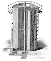
Larger sizes of water-cooled condenser require closer packing of the tubes to minimize the overall size, and the general form is shell and tube, having the water in the tubes. This construction is a very adaptable mechanical design and is found in all sizes from 100 mm to 1.5 m diameter and in lengths from 600 mm to 6 mm, the latter being the length of commercially available tubing. Materials can be selected for the application and refrigerant, but all mild steel is common for fresh water, with cupronickel or aluminum brass tubes for salt water.
Some economy in size can be affected by extended surfaces on the refrigerant side, usually in the form of low integral fins formed on the tubes. On the water side swirl strips can be fitted to promote turbulence, but this interfere with maintenance cleaning and are not much in favor. Water velocity within the tubes is of the order of 1m/s, depending on the bore size. To maintain this velocity baffles are arranged within the end covers to direct the water flow to a number of tubes in each pass. Some condensers have two separate water circuits, using the warmed water from one circuit as reclaimed heat in another part of the system. The main bundle rejects the unwanted heat. Where the mass flow of water is unlimited (sea, lake, river, or cooling tower), the temperature rise through the condenser may be kept as low as 5 K, since this will reduce the in MTD with a lowering of head pressure at the cost only of larger water pumps and pipes.
Shell-and-tube condensers can be installed with the axis vertical and will be one-pass, the water falling to an outlet tank below. This arrangement permits tube cleaning while the plant is operating.
The supply of water is usually limited and requires the use of a cooling tower. Other possibilities are worth investigation; for example, in the food industries, large quantities of water are used for processing the product, and this could be passed first through the condensers if precautions are taken to avoid contamination. Also, where ground water is present, it could be taken from a borehole and afterwards returned to the ground at some distance from the suction. In both the cases, water would be available at a steady temperature and some 8-10 K colder than summer water from a cooling tower.
Cooling Towers
In a cooling tower, cooling of the main mass of water is obtained by the evaporation of a small proportion into the airstream. Cooled water leaving the tower will be 3-8 K warmer than the incoming air wet bulb temperature. The quantity of water evaporated will take up its latent heat equal to the condenser duty, at the rate of about 2430 KJ/KG evaporated, and will be approximately
1/2430 = 0.41 × 10ˉ3 KG(s KW)
And, for the plant capacity, would evaporate at 0.18 KG/s.
Cooled water from the drain tank is taken by the pump and passes through the condenser, which may be building up with the compressor as part of a compressor-condenser package (condensing unit). The warmed water then passes back to sprays or distribution troughs at the top of the tower and falls in the up going airstream, passing over packing which presents a large surface to the air. Evaporation takes place, the vapor obtaining its latent heat from the body of the water, which is therefore cooled.
Evaporative Condensers
This cooling effect of the evaporation of water can be applied directly to the condenser refrigerant pipes in the evaporative condenser. The mass flow of water over the condenser tubes must be enough to ensure within of the tube surface, and will be of the order of 80-160 times the quantity evaporated. The mass flow of air must be sufficient to carry way the water vapor formed, and a compromise must be reached expected variations ambient conditions. An average figure is 0.06 KG/(s KW).
It will be seen that the water and air mass flow rates over a cooling tower are roughly equal.
Evaporative condensers have a higher resistance to air flow than cooling towers and centrifugal fans are often used, ganged together to obtain the required mass flow without undue size. This arrangement is also quieter in operation than axial flow fans. Most types use forced draught fans.
Cooling towers and evaporative condensers may freeze in winter if left operating on a light load. A common arrangement is to switch off the fans with a thermostat, to prevent the formation of ice. The water-collection tank will have an immersion heater to reduce the risk of freezing when the equipment is not in use or tank may be located inside the building under the tower structure, if such space is conveniently available.
Materials of construction must be corrosion resistant. Steel should be hot galvanized, although some resin coatings may suffice. GRP casings are used by some manufacturers. The water-dispersal packing of a cooling tower is made of treated timber or corrugated plastic sheet.
The atmospheric condenser is a simplified form of evaporative condenser, having plain tubes over a collecting tank and relaying only on natural air draught. This will be located on an open roof or large open space to ensure a good flow of air. The space required is of the order of 0.2 square meter per KW and such condensers are not much used because of this large space requirement. Atmospheric condensers can steel seen on the roofs of old breweries. They are in current use where space is plentiful.
Water Treatment
All water supplies contain a proportion of dissolved salts. These will tend to be deposited at the hottest part of the system, e.g. the furring of a kettle or hot water pipes. Also, these impurities do not evaporate into an airstream, so where water is being evaporated as part of the cooling process, the salts will remain in the circuit and increase in concentration, thus hastening the furring process.
It is possible to remove all solids from the make-up water, but it is much cheaper to check the concentration by other means. Two general methods are employed. The first relies on physical or chemical effects to delay deposition of scale on the hot surfaces; the second restricts the concentration to a level at which precipitation will not occur. In both cases, the accumulation of solids is removed by bleeding off water from the circuit to drain, in addition to that which is evaporated.
The concentration of solids in the circulating water will increase until the amount carried away by the bleed water compensates for that not carried away in the water vapor. So, if
Cm = Concentration of solids in make-up water (Kg/Kg)
Cb = Concentration of solids in bleed-of (Kg/Kg)
We = Mass flow of water evaporated (Kg/s)
Wm = Mass flow of make-up water (Kg/s)
Therefore, Mass of solids entering = Mass of solid leaving
Cm × Wm = Cb × (Wm- We)
Wm = We ((Cb/ (Cb-Cm))
The concentration of mains make-up water, Cmv is obtained from the water supply authority. The permissible concentration, Cb, will be decided by the method of water which will prevent precipitation.
In all cases where water is used for cooling, but more specially it is being evaporated, the hardness figure should be obtained from the local water supply authority. Enquiries should also be made as to possible variations in the supply, since many cities draw their water from two or more catchment areas, and the type and quantity of hardness may change.
Many suppliers now offer water treatment for use in refrigeration considers circuits, and the merits of different methods need to be assessed before making a choice. The reader is referred to specialist works on the subject.
There are several methods of providing a percentage ‘bleed-off’ from the water circuit:
- The make-up ball valve can be set a little high so that some water always goes down the overflow pipe. This is rather difficult to ser initially, but is reliable and cannot easily be tempered with. It will work at all times, and so will waste water if the plant is not running.
- A small bleed-off pipe is taken from the pump discharge, with an adjusting valve, and led to waste. This can be more easily adjusted and works only when the condenser is running, but is subject to interference by unauthorized persons.
- Tarnish, having an area possibly 1% of the cross-sectional area of the tower, is located just above the water level and is led to the drain, formatting part of the overflow fitting. This will bleed off 1% of the water falling through the tower.
All this methods provide the maximum required rate of bleed-off at all times of the year, and so will waste water at light load conditions. The user should be aware of the essential nature of bleed-off, since cases often occur in dry weather of misguided persons closing off the bleed to ‘save water’.
In some locations, it is necessary to drain the tank frequently to clear other contaminants. With careful control, this can be used as the necessary bleed-off.
Ratings and Sizing of Condensers
Catalogue ratings show heat rejected at a stated condensing temperature and related to the following:
- Ambient dry bulb temperature for air-cooled condensers
- Available water temperature for water-cooled condensers
- Ambient wet bulb temperature for evaporative types
Choice of equipment based on first cost only will almost certainly result in an undersized condenser and a high head pressure.
Condenser Maintenance
As with any mechanical equipment, condensers should never be located where they are difficult of access, since there will then be less chance of routine maintenance being carried out. Periodic maintenance of a condenser is limited to attention to the moving parts – fans, motors, belts, pumps, and cleaning of water filters, if fitted.
The overall performance will be monitored from the plant running log and the heat exchange surfaces must be kept clean for maximum efficiency- meaning the lowest heat pressure and lowest power.
Air – cooled surfaces may be cleaned by brushing off the accumulation of dust and fluff where the air enters the coil, by the combination of a high-pressure air hose and a vacuum cleaner, or, with the obvious precautions, by a water hose. Foaming detergents are also used.
Advance warning should be had from the plant running log of any build-up of scale on water-cooled surfaces. Scale within the tubes of a straight double-pipe or shell-and-tube condenser can be mechanically removed with suitable wire brushes or high-pressure water lances, once the end covers have been removed. Tubes which cannot be dealt with in this way must be chemically cleaned.
It will be appreciated that, where air and water are present, as in water cooling tower or evaporative condenser, the apparatus will act as an air washer, removing much of the dust from the air passing through it. Such dirt may be caught in fine water, but is more commonly allowed to settle into the bottom of the tank and must be flushed out once or twice a year, depending on the severity of local contamination. Where heavy contamination is expected, it is good practice to provide a deeper tank than usual, the pump are in use. Where plant security is vital, the tank is divided into two parts, which may be cleaned alternately.
Algae and other organisms will tend to grow on wet surfaces, in particular those in daylight. Control of this can be affected by various proprietary chemicals.
Cooling towers and evaporative condensers release into the atmosphere fine droplets of water, which may carry sources of contamination such as algae and bacteria. Many of this thrives at the temperatures to be expected in water cooling systems and one of them, Legionella, pneumophila, has been identified as a particular hazard to health. Cooling apparatus should be cleaned and disinfected frequently to reduce these risks of contamination and should not be located where water droplets can be drawn into ventilation air intakes.
It is now some 20 years since the recognition of Legionella pneumophila in condenser water, and the measures taken by industry to combat the hazards to human health. Worldwide indications are that the initial vigilance and care have lessened in recent years and attention is now drawn again to such precautions.
Condenser Fittings
The inlet pipe bringing high-pressure gas from the compressor must enter at the top of the condenser, and adjacent piping should slope in the direction of flow so that oil droplets and any liquid refrigerant which may from will continue in the right direction and not back to the compressor.
The outlet pipe must always be from the lowest point, but may have a short internal up stand so that any dirt such as pipe scale or metal swarf will be trapped and not taken around the circuit.
Condensers for ammonia systems may have an oil trap, usually in the form of a drain pot, and the liquid outlet will be above this
Water connections to a shell-and-tube condenser must always be arranged so that the covers can easily be removed for inspection, cleaning, and repair of the tubes. Heavy end covers require the use of lifting tackle, and supports above the lifting points should be provided on installation to facilitate this work.
Condensers having a gross volume of more than 285 liter are required under BS 4434: 1980 to have two pressure relief valves or two bursting discs, one always in service. Those have below 85 liter but larger than 76 mm inside diameter may have a fusible plug to relive pressure in a fire. Manufactures will be aware of the requirements of this BS and similar standards, and proprietary products will be correctly equipped.
Other forms of Condenser
In a cascade system, the evaporator of the high stage is the condenser for the low stage. Construction of this heat exchanger will be a combination of the design factors for evaporators and condensers, and no general rules apply apart from these. The inter-cooler of a two stages or compound system de-superheats the discharge gas from the first stage so that it will not be too hot on entering the high stage. In practice, it will leave the intercooler only slightly superheated above the inter stage saturation point. The normal fluctuations in an operating system may lead to actual condensation at times, but is not so intended.
The small condensing surface required by a domestic appliance such as a deep freeze may allow the use of the outside metal skin of the appliance itself as a surface condenser. In such a construction, the condenser tube is held in close mechanical contact with the skin, so that heat is conducted through to the outside air, where it is lost by natural convection. This system is restricted to a few hundred watts.
Winter Operation
Condensers are sized so that they can reject the system heat load under maximum conditions of air or water temperature. In colder weather, the condensing temperature will fall with that of the cooling medium and these may cause difficulties in correct operation of the plant. In particular, the pressure across the expansion valve may be too low to circulate the required mass flow of the refrigerant. Under such circumstances, artificial means must be used to keep the head pressure up, always remembering that the condensing pressure should be kept as low as practical for power economy. Various systems are used:
- Air-cooled condensers having two or more fans may have a pressure switch or thermostatic control to stop the fans one by one. This method is simple, cheap, and effective.
- The fans on such condensers may be fitted with two-speed motors or other speed control. It should borne in mind that, if one fan of a pair stops, the noise level will fall by 3 db, but if both fans drop to half speed, the noise drop by 15 db. This method is of special use in residential areas where the greater noise level will be tolerated in the day time when condensing air is warmest, but a lower fan speed can be used at night.
- Evaporative condensers and water cooling towers with two or more fans on separate drive may be controlled in the same way. If a single motor drives several fans in one shaft, speed control or dampers will be required. Evaporative condensers and cooling towers should be fitted with antifreeze thermostats which will stop all fans before the water reaches freezing point.
- Cooling air flow can be restricted by blanking flaps, baffles or winter enclosures, providing that, if not automatic, the operating staff are aware of their presence and will restore the air flow when the weather turns warm again.
- Water flow may be restricted by throttling valves. One such device is operated directed by head pressure, but electric or pneumatic throttling or flow diversion valves can be applied for the purpose.
- A set pressure bypass valve can be fitted across the condenser, so that hot gas will pass directly to the receiver in cooler weather. This will cause the condenser to partially fill with liquid refrigerant, thus decreasing the heat transfer surface available for condensation. Sufficient refrigerant must be available for this, without starving the rest of the circuit.
- Where a complex system is served by two or more condensers, a complete condenser can be taken off line by a pressure switch.
Apart from such requirements for head pressure control, winter precautions are needed to prevent freezing of the water while the plant is not rejecting heat to it. These commonly take the form of an electric immersion heater in the water tank, together with lagging and possible trace heating of exposed pipes. In some systems, the evaporative condenser itself may be within the building, with air ducts to the outsides. In severe climates, external tanks need to be lagged to conserve the heat providing by the immersion heater.
Receivers
The total refrigerant charge required in a circuit will vary with different operating loads and ambient, and must be sufficient at all times so that only liquid enters the expansion valve. This implies that, at times, the circuit would have too much charge, which would back up in the condenser and reduce its efficiency. A drain tank is required directly after the condenser which can hold this reserve of liquid, and is termed the receiver.
Receivers also act as pump-down tanks, and should be capable of holding enough of the total refrigerant charge to permit evacuation of any one vessel for maintenance, inspection or repair. They should never be more than 85% full, to allow for expansion and safety.
Receivers are commonly made of steel tube with welded dished ends, and are located horizontally. Small receivers may be vertical, for convenience of location. The liquid drain pipe from the condenser to the receiver should be implying sized, and any horizontal runs sloped to promote easy drainage. Shut-off valves in this line should not be in a horizontal outlet from the condenser, since their slight fictional resistance will cause liquid back-up in the condenser. Outlet pipes from the receiver may be from the bottom or, by means of an internal stand pipe, may leave at the top. A valve is invariably fitted at this point.
Ammonia receivers may have an oil drum pot, and the receiver will slope slightly down towards this.
Receivers are pressure vessels covered by the provisions of BS 4434: 1980 and require safety pressure relief devices as outlined. In case where there is no shut-off valve between the condenser and receiver, such protection may be fitted to one or the other, providing the total volume is considered.
In practice, receivers will operate about one- sixth full during normal running. Some means are usually provided to indicate the liquid level inside. These are as follows:
- An external, vertical slight glass, of suitable pattern, having self-closing shut-off valves.
- A number of bulls –eye glasses, arranged at different heights in the shell.
- A pair of bulls –eye glasses, arranged on the same cross-section and some 45º up from the horizontal diameter. A light is shone through one and the observer looks through the other.
Dry coolers
The water-cooled condensers, cooling towers and evaporative condensers described 5.4, 5.5 and 5.6 all use water at a temperature which will promote the growth of the bacterium Legionella Pneumophila. While correct water treatment and other precautions are 100% safe against this trouble, users may prefer to avoid any risk by using a sealed water system. Such heat exchangers are generally termed dry coolers. They are of similar construction to air cooled condensers. The cooling of water or industrial fluid, other than refrigerant, will follow a similar design. The fluid is circulated through the tubes of the heat exchanger, while blowing air over the outside. The tubes will usually have an extended surface.
The use of dry coolers cannot take advantage of the lower cooling temperatures available by the evaporation of the cooling water, and is limited by the ambient dry bulb temperature, rather than the wet bulb. Higher power is therefore required, and a given size compressor.