Instrument of Current Transformer:
The instrument current transformer (CT) steps down the current of a circuit to a lower value and is used in the same types of equipment as a potential transformer. This is done by constructing the secondary coil consisting of many turns of wire, around the primary coil, which contains only a few turns of wire. In this manner, measurements of high values of current can be obtained. A current transformer should always be short-circuited when not connected to an external load. Because the magnetic circuit of a current transformer is designed for low magnetizing current when under load, this large increase in magnetizing current will build up a large flux in the magnetic circuit and cause the transformer to act as a step-up transformer, inducing an excessively high voltage in the secondary when under no load. [Reference-1]
Application of Current Transformer:
Direct measurement of current in high voltage system is not possible because of insulation problem of measuring instruments. It is also not possible to use current flowing through the system directly for protection purpose due to its high value and high insulation problem.
Basic Function of Current Transformer:
- To reduce the line current to a value which is suitable for standard measuring instrument, relay etc.
- To isolate the measuring instruments namely meters, relays etc. from high voltage side of an insulation.
- To protect measuring instruments against short circuit currents
- To sense abnormalities in current and to give current signals to protective relays to isolate the defective system.
Theory of Current Transformer:
A Current Transformer (CT) operates on the principle of balance of Ampere-Turns (AT) in primary and secondary winding. Theory of CT can easily be understood with the help of vector diagram of figure.
Voltage ES developed across secondary of the CT can be represented as![]()
Where,
ZS is impedance of burden connecting leads and CT secondary.
The flux () required to develop voltage ES needs excitation current I0. This excitation Ampere-Turns (AT) are supplied through total primary AT causing error in the transformation ratio of the CT. Due to non-linear characteristics of magnetic material, errors in the CTs are also non-linear over the current range of 120% to 5%.
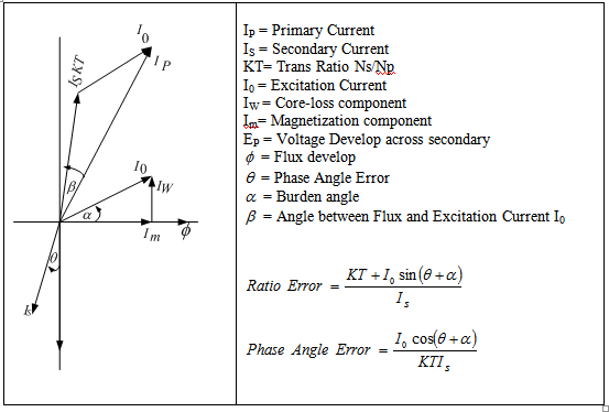
Figure: Vector Diagram of Current Transformer
There are four main factors which determine the capability of CT. They are:
- Insulation level (service voltage)
- Rated primary current
- Short time withstand current
- Burden and accuracy
The Current Transformer must:
- Withstand operational voltage and over voltage in the network.
- Withstand rated primary current in continuous operation without exceeding maximum allowed temperature rise.
- Capable to sustain thermal and mechanical stresses developed due to system fault current.
- Feed current to external circuit with specified accuracy at specified primary current.
[ Reference-2]
VOLTAGE TRANSFORMER
Instrument of Potential Transformer
The instrument potential transformer (PT) steps down voltage of a circuit to a low value that can be effectively and safely used for operation of instruments such as ammeters, voltmeters, watt meters, and relays used for various protective purposes. The potential transformer works along the same principle of other transformers. It converts voltages from high to low. It will take the thousands of volts behind power transmission systems and step the voltage down to something that meters can handle. These transformers work for single and three phase systems, and are attached at a point where it is convenient to measure the voltage.
Application of Potential Transformer
Direct measurement of current in high voltage system is not possible because of insulation problem of measuring instruments. It is also not possible to use direct voltage for the system protection purpose due to its high value and high insulation problem of protective relays. Therefore, Voltage Transformers or Potential Transformer (PT) is used to step-down the high system voltage to low standard value accurately in proportion to their ratio. [Reference-3]
Basic Function of Potential Transformer
- To reduce the line voltage to a value which is suitable for standard measuring instrument, relay etc.
- To isolate the measuring instruments namely meters, relays etc. from high voltage side of an insulation.
- To sense abnormalities in voltage and to give voltage signals to protective relays to isolate the defective system.
Theory of Potential Transformer
General principles of power transformer design also apply to the PTs but there are certain considerations of performance which are of particular importance. In the electromagnetic PTs, accuracy depends on leakage reactance and winding resistance. These determine how the phase error and voltage error vary as the burden on secondary increase.
The permeability and power dissipation of core material affects the exciting current and thus the error at zero burdens. To comply with the requirement of IEC186/ ANSI C 57.13 standard, flux density in PT is much less than the value generally used in power transformer. The turn ratio and voltage drop due to leakage reactance and the winding resistance must be carefully determined, in order that the permissible error is not exceeded.
Theory of voltage transformer can be established more clearly with the help of phasor diagram as given in figure by Reference-4]
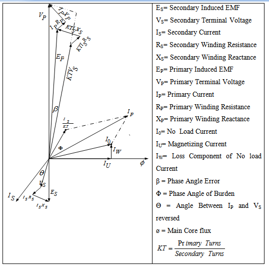
Figure : Vector Diagram of Potential Transformer
Potential Transformer consists
- Primary and Secondary Winding
- Electromagnetic Core
- Bottom Tank and oil Expansion Chamber
- Porcelain Bushing
SELECTION OF POTENTIAL TRANSFORMER
- Service Voltage system voltage in which PT is to be installed.
- Installation whether outdoor or indoor
- Atmospheric Conditions such as condition of pollution, altitude, ambient temperature etc.
- Insulation level if insulation level other than associated with service voltage is required, it should be specifically mentioned.
- Rated Primary Voltage is generally rated system voltage for un-earthed type PTs and rated system voltage divided by square root of three for earthed type PTs. The PTs can be manufactured suitable for more than one system voltage. In such cases, different primary voltages required may be indicated.
- Rated Secondary Voltage standard values of secondary voltages are 110V or Volt depending on application of the secondary winding. PTs with different for different; earthing system. Therefore appropriate system earthing conditions may be specified.
- Voltage Factor all PTs are manufactured for
- Continuous voltage factor of 1.2
- As per IEC/IS specifications
- Short-time voltage factor is different for different; earthing systems.
Single phase electromagnetic PT is manufactured in two types:
- Single Pole (Between lines and earth)
- Double Pole (Between line-to-line)
Three-phase PTs are of star/star connected or Star/open delta connected (Residual Voltage Transformer) type.
Single phase PTs are connected for 11kV to 230kV system voltage, whereas 3-phase PTs are connected for 11kV to 33kV system voltage.[ Reference-5]
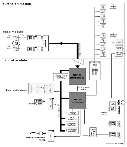
Analogue measured value detection
Current measuring
For measuring the relevant currents there is a separate transducer for each of the existing measured quantities. This transducer provides galvanical isolation to the relay electronics. Adjustment to the main CT rated currents is realized via the software. The input signal is
Transmitted by internal CTs up to 64 times rated current linear. To achieve an utmost accuracy there are two current measuring ranges, changeover of which is automatically. Each channel has its own sample-and-hold circuit. All channels are scanned simultaneously. [Reference-6]
Digital signal processor
The digital signal processor (DSP) in the relay is mainly used for processing measured values by controlling and monitoring data entry from the different measuring channels. In addition all input signals are digitally Fourier filtered. Among other values this processor calculates RMS values and stores digitalized signal sequences to the memory and the signal recorder (option). Apart from data management and processing the DSP keeps performing wide-ranging self-tests. [Reference-6]
Digital main processor
The main processors is the highest control element within the relay and processes the actual protection program which interprets data obtained by the DSP and so refers to the operational status of the object to be protected and to the own device. Special protection mechanism enable the MRDG to detect problems in the own hardware. All communication between relay and the outside world is also controlled by the main processor. This does not only mean control of indications or handling of key inputs but also harmonizing the different data interfaces as well as control of output relays. [Reference-6]
Block Diagram of Extension Module
connection
The right polarity of the C.T. is very important and so when the relay is initially connected this has to be checked carefully. Reverse polarity at even one C.T. only is likely to cause trip errors. Whether connection of the relay is correct can roughly be seen from the differential current indication, provided the object to be protected operates trouble free. To check the correct C.T. connection, firstly the Differential Protective relay should be operated at the object to be protected in OFFLINE TEST mode. [Reference-7]
Important Note:
In this operational mode, the object to be protected must have a sufficient back-up protection. Furthermore it is assumed that the supervised component is not faulty and all parameters are correct. When in OFFLINE TEST mode it is ensured that a CT with perhaps reverse polarity does not cause an unintended trip.
Now the supervised component can be switched on while observing and interpreting the differential current indication. Interpretation of the indicated value is always subject to local conditions (operation related fault current) and can here only be described generally. The test circuits described in chapter 6 can be of help for fault identification.
The following table can be considered as reference when checking the connection. The stated values are based on symmetrical load I = IL1=IL2=IL3. Where loads are involved which are not 100 % symmetrical, the observed values may deviate from the table. All figures are to be understood as approximate values and are a multiple of the load current.
Sl.No | Case | Differential Current Idiff / In | Through Current Is / In |
1 | All CTs are correctly connected | 0 | 1 |
2 | One CT connect with rev. polarity | 1.33 | 0.66 |
3 | Two CTs connect with rev. polarity | 2.0 | 0 |
4 | Three CTs connect with rev. polarity | 2.0 | 0 |
Table 5.1: Tested values for differential Current and stabilizing current indication at the relay with assumed faultless components a different number of CTs connected.
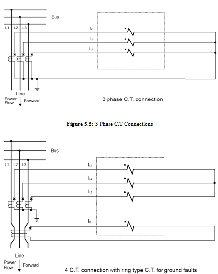
- Correct connection:
All C.Ts are correctly connected. This case is identical to that where all C.Ts are wrongly connected or the direction of energy flow is reverse. But changes at the C.T. connection are not necessary.
- One C.T. wrongly connected
In this case the current balance is out of place. There is about 1/3 x I through current missing and the relay recognizes 2/3 x I differential current instead. Input and output currents in the phase with wrong polarity are interpreted by the Differential relay that way as if 1/3 x I each flow into the faulty phase. Thus the resulting differential current is 2/3 x I. 3 / 4) two or three C.Ts wrongly connected In these two cases the indication does not distinguish between two or three C.Ts wrongly connected because of the internal calculation. If three CTs are wrongly connected, the respective fault can be eliminated by changing parameter “C.T. Connection” without having to change the wiring.
For locating all other faults either the complete C.T. wiring has to be checked after disconnection of the component or the reversed connections to be traced by means of a suitable test current source. [Reference-6]
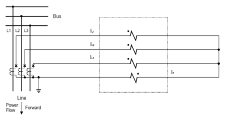
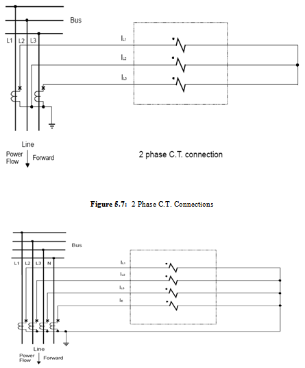
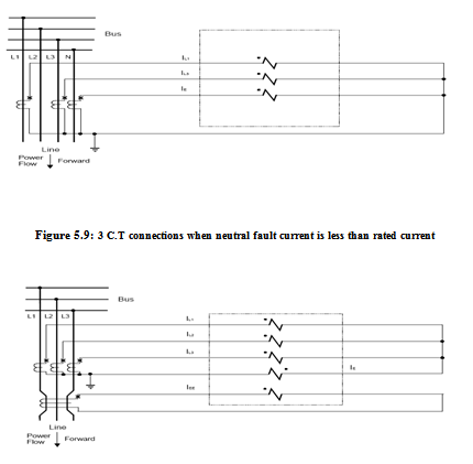
Figure : 3 Phase C.T Connections with residual connection for neutral faults
Requirement of Current Transformers for Differential Protection (Static Schemes)
Differential protection should preferably be fed from its own current transformers which are then loaded only by the secondary leads and any auxiliary C.T’s. In static protective systems, the power consumption of the protection itself is negligible. The line as well as the auxiliary C.T’s with the secondary burden should have an accuracy limit factor corresponding to the maximum through fault current and at least 20 times rated current. The ratio and the connection of the auxiliary C.T’s are so determined that the secondary currents are balanced. The secondary currents of power transformers with tap changers should be balanced at the average ratio of the transformers.
When the differential protection is to be installed at a large distance from the line C.T’s the auxiliary C.T’s should be located close to the line C.T’s. They should have a current rating that reduces the power consumption of the secondary leads to the protection to a value acceptable in each case. This is especially necessary when the differential protection also protects a long feeding cable (transmission cable). In that case it is necessary to reduce the rated current of the secondary leads (pilot wires) to 0.3 or 0.2 A. A set of auxiliary C.T’s are used with the line C.T’s at the line end and a further set close to the differential protection to obtain rated currents of I or 5A for the relay. When the quality or the location of the secondary leads is such that failures are possible, a protective resistor or similar component should be connected in to the leads. Open secondary circuits may mean damage to the line C. T’s and the auxiliary C.T’s
[ Reference-9]
Operational TECHNIQUE
Fault is created on the stator winding. On the both sides of stator winding current meters are connected which represents current transformers. These current meter measures current entering into stator windings, which are called starting end currents represented as IaS, IbS, and IcS for three phases a, b, c respectively as shown in figure 2.
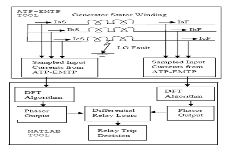
Figure : Block diagram of proposed scheme
Similarly, currents at the other end of stator winding called as finishing end currents are represented as IaF, IbF and IcF are measured by current meters at that end. Ground fault is created at the midpoint of stator winding of one of the phase. Fault data measured by current meters at both end of stator windings is stored in a file.
Real and imaginary components of these current phasors at both ends of stator winding are compared. It is observed that, under no fault condition, difference of real and imaginary components of current at the both end is zero and under fault condition, it is greater than zero. Based on this analysis, differential relay logic is applied and relay trip or no-trip decision is taken. Single line to ground fault and line to line fault, internal and external to the stator winding are simulated and results are discussed as a case study in next section. [ Reference-9]
Case Study
Single line to ground and line to line faults are simulated on synchronous machine stator winding which is analyzing of these faults is illustrated below.
Internal Fault
Single line to ground fault is simulated at the midpoint of phase ‘a’ stator winding as shown in figure 1. Currents entering stator windings are shown in figure 3 below.
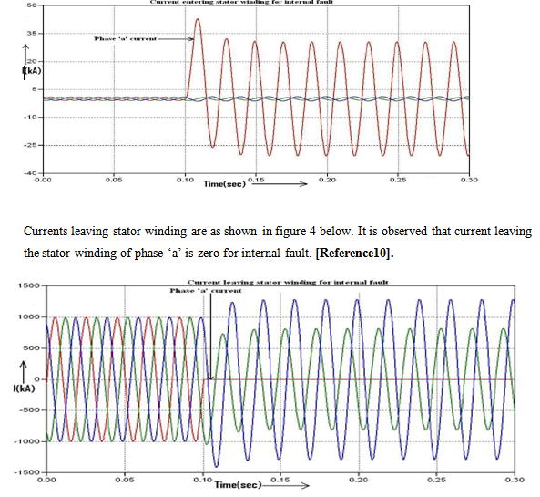
Figure: Current leaving stator winding
Similarly line to line fault is simulated at the midpoint of phase ‘a’ and phase ‘b’ of stator winding. Currents entering stator windings are shown in figure 5 below.
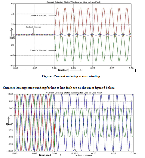
Figure: Current leaving stator winding
These currents at starting end and at finishing end of stator windings are stored in a file and processed in MATLAB. Currents at both ends are in sampled form and recursive DFT algorithm is applied to calculate fundamental frequency phasor. Both magnitude and phase angles are calculated.
Magnitudes of currents at both ends of stator windings for single line to ground fault are as shown in figure 4.16 (a) and (b) below. [Reference-10].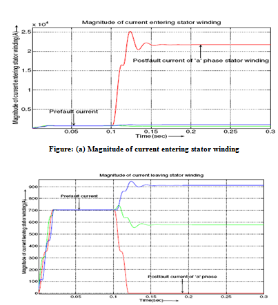
Figure: (b) Magnitude of current leaving stator winding
Magnitudes of currents at both ends of stator windings for line to line fault are as shown in figure 4.17 (a) and (b) below.[ Reference-11] .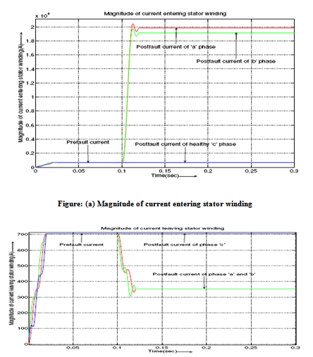
Figure: (b) Magnitude of current leaving stator winding
Phase angles of currents at both ends of stator windings for single line to ground fault are as shown in figure 4.18 (a) and (b) below.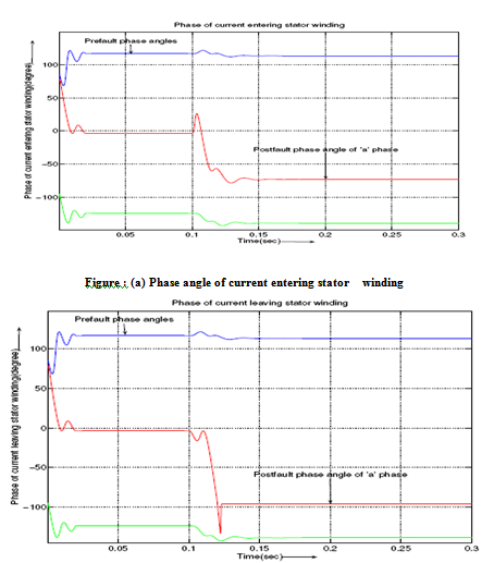
Figure: (b) Phase angle of current leaving stator winding
From above figure 4.17 (a) and (b), it is observed that after fault inception on phase ‘a’ stator winding at 0.1s, current at starting end rises to high value and current at photofinishing becomes zero. From figure 4.18 (a) and (b), it is observed that after fault inception, there is unbalance in the phase angles of currents at
Both ends. Similarly, unbalance in the phase angles is also observed in case of line to line fault.
After calculating magnitude and phase angle of currents at both ends of stator windings, there real and imaginary components are calculated. For single line to ground fault, the difference of real and imaginary components of currents at both ends is taken and is as shown in figure 4.19 (a) and (b) below. [Reference-10].
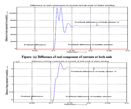
Figure: (b) Difference of imaginary component of currents at both ends
From figure 4.19 (a) and (b), it is observed that, during pre-fault condition, difference of currents at both ends is zero for both faulty as well as healthy phases. After fault inception, this difference rises to very high value for faulty phase. This change in difference of currents at both ends is used for fault discrimination and also to generate the trip signal for circuit breaker.
Differential relay logic is developed based on the change in difference of real and imaginary components of currents at both ends of stator winding. Figure 4.20 shows the
trip signal. It is observed that at 0.1s relay issues trip signal.
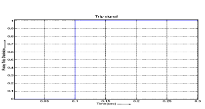
Figure: Trip signal
Similar analysis is carried out for line to line fault and generates the trip signal.
External Fault
Single line to ground fault is simulated at the terminal of phase ‘a’ stator winding as shown in figure 1. If single-line to ground fault occurs on terminal of synchronous generator that is external to the stator winding, then currents at both ends of stator windings remains same as shown in figure 4.21 (a) and (b) below.
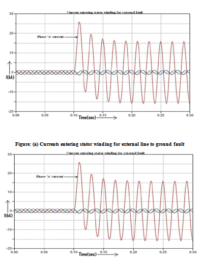
Figure: (b) Currents leaving stator winding for external line to ground fault
If line to line fault occurs on terminal of synchronous generator that is external to the stator winding, then currents at both ends of stator windings remains same as shown in figure 4.22 (a) and (b) below.
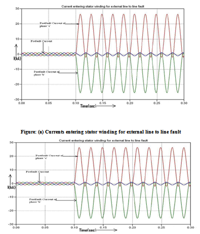
Figure: (b) Currents leaving stator winding for external line to line fault
Therefore, for fault external to the stator winding, differential relay does not issue trip signal. Figure 4.23 (a) and (b) shows the magnitude of currents at both ends of stator winding for external single line to ground fault.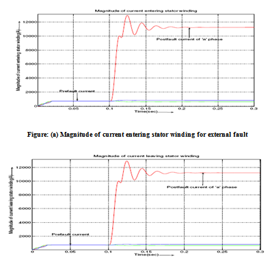
Figure: (b) Magnitude of current leaving stator winding for external fault
From figure 14 (a) and (b), it is observed that magnitude of currents at both ends remains same. Figure 4.24 (a) and (b) shows phase angles of currents at both ends for the single line to ground fault external to the stator windings. [Reference-11]
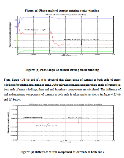
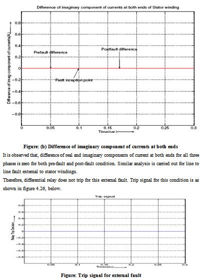
Figure: Trip signal for external fault
Similar analysis is carried out with double line to ground fault internal to stator windings and external to stator windings. It is observed that differential relay does not trip for external fault and issues trip signal for internal fault.
Bibliography
[1] “Protective Relays Applications Guide,” The English Electric Company Limited,
Relay Division, Stafford, 1975.
[2] C. J. Mozina, IEEE Tutorial on the Protection of Synchronous Generators, IEEE
Tutorial Course, IEEE Power Engineering Society Special Publ., no. 95 TP102, 1995.
[3] A. I. Megahed, Student Member, IEEE, and O. P. Malik, Fellow, IEEE, “An Artificial neural network based digital differential scheme for synchronous generator stator winding protection,” IEEE Transactions on Power Delivery, vol 14, January 1999.
[4] M. S. Sachdev (Coordinator) Microprocessor Relays and Protections Systems, IEEE Tutorial Course Text, Power Engineering Society Special Publ. No.88 EH0269-1-PWR, IEEE, Piscatway, NJ, USA, 1988.
[5] Gabriel Benmouyal, Serge Barceloux, and Rolland Pelletier, “Field experience with a digital relay for synchronous generators,” IEEE Transactions on Power Delivery, vol. 7, no. 4, October 1992.
[6] M. S. Sachdev and D. W. Wind, “Generator differential protection using a hybrid computer,” IEEE Trans. Power Apparatus System, PAS-92 (1973) 2063-2072.
[7] H. Tao and I. F. Morrison, “Digital winding protection for large generators,” J. Electr. Electron. Eng. Aust., 3 (1983), 316-321.
[8] P. K. Dash, O. P. Malik, and G. S. Hope, “Fast generator protection against internal asymmetrical faults,” IEEE Transactions on Power Apparatus and Systems, vol. PAS-96, no. 5, September/October 1977.
[9] P. K. Dash, O. P. Malik, and G. S. Hope, “Digital differential protection of a generating unit scheme and real-time test results,” IEEE Transactions on Power Apparatus and Systems, vol. PAS-96, no. 2, March/April 1977.
[10] http://www.google.com
[11]http://www.wikipedia.org/w/index.php?title=Special%3ASearch&redirs=1&search=Magnitude+of+current+entering+stator+winding+for+external+fault&fulltext=Search&ns0=1