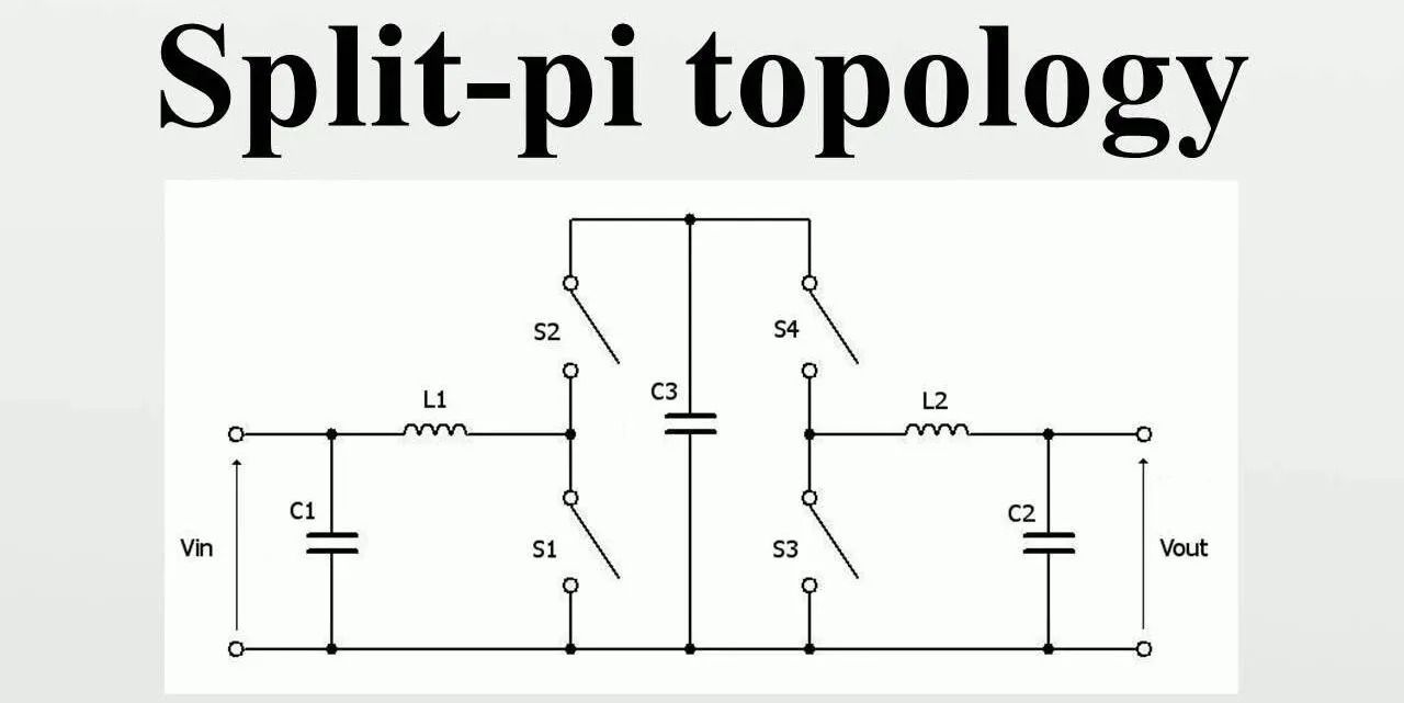
Split-pi topology is a typical arrangement found in electrical circuits, particularly power supply and amplifiers. In electronics, it is a pattern of component interconnections used in a type of power converter that can theoretically create any output voltage, either higher or lower than the input voltage. It is a modification of the classic Pi (π) architecture, which comprises of an input capacitor, next an inductor, and finally an output capacitor.
In fact, the maximum voltage output is restricted by the voltage ratings of the components utilized. It’s basically a boost (step-up) converter followed by a buck (step-down) converter. MOSFETs are naturally bidirectional due to their design and function, making them ideal for applications needing regenerative braking. The split-pi arrangement divides the inductor into two sections, each coupled to the input and output capacitors.
The split-pi converter is a type of DC-to-DC converter whose output voltage magnitude is either larger than or less than that of the input voltage. It is a switched-mode power supply with a circuit similar to a boost converter followed by a buck converter. Split-pi gets its name from the pi circuit due to the use of two pi filters in series and split with the switching MOSFET bridges.
Other DC–DC converter topologies that can produce output voltage magnitude either greater than or less than the input voltage magnitude include the boost-buck converter topologies (the split-pi, the Ćuk converter, the SEPIC, etc.) and the buck–boost converter topologies.
The split-pi configuration offers several advantages over the traditional Pi configuration:
- Improved High-Frequency Performance: By splitting the inductor into two parts, the split-pi configuration can reduce the parasitic capacitance between the inductor and the ground, leading to better high-frequency performance.
- Reduced Component Size: Splitting the inductor allows for the use of smaller inductors compared to the traditional Pi configuration, which can lead to space savings and potentially cost savings.
- Enhanced Stability: Splitting the inductor can also improve the stability of the circuit, especially in applications where stability is critical, such as in voltage regulators.
- Lower EMI: Splitting the inductor can help to reduce electromagnetic interference (EMI) emitted by the circuit, which is beneficial in applications where EMI must be minimized.
Overall, the split-pi topology is a versatile configuration that can offer improved performance and efficiency compared to traditional Pi configurations, especially in high-frequency applications.