![Report on L/C Tracking System of HSBC [part-2]](https://assignmentpoint.com/wp-content/uploads/2013/03/hsbc1.jpg)
4. System Analysis
4.1 Systems Analysis
Before moving to the broader horizon of systems analysis it is necessary to shed some light about the core concepts of system and information system.
Dewitz (1996) stated, a system is a set of interrelated components that work together in a particular environment to perform whatever functions are required to achieve the system’s objectives. Each of these components is very critical to the makeup of the system. These components must be interrelated for the system to work properly. A system has three basic functions 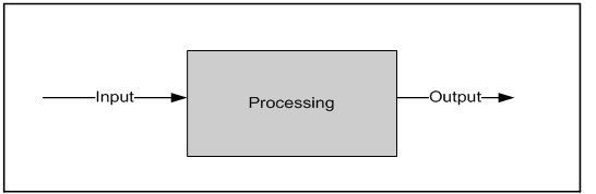
Figure 4.1: Basic functions of a system
Input: Input involves capturing and assembling elements that are to be entered and processed in the system.
Processing: Processing involves transformation process that converts inputs into outputs.
Output: Output involves transfer of elements that have been produced by a transformation process to their ultimate destination.
4.2 Information System
A system that accepts data from its environment (input) and manipulates the data (processing) to produce information (output). An information system is a data processing system that engages in collecting, processing, editing, storing, transmitting and supplying data relating to a certain area of application.
The term information system is normally used in a narrower sense to refer to an automated system, It then refers to the applications in combination with the IT infrastructure. In a wider sense the information system includes all the procedures and resources in connection with the data of a certain area of application. A non-automated administrative system is therefore an information system, too.
Taking as an example, LC tracking system – processing system, which accepts inputs (shipment and delivery data) from its environment – external environment government regulations, competitors and internal environment – end users, organizational polices and processes this data to produce outputs (goods arrival date). 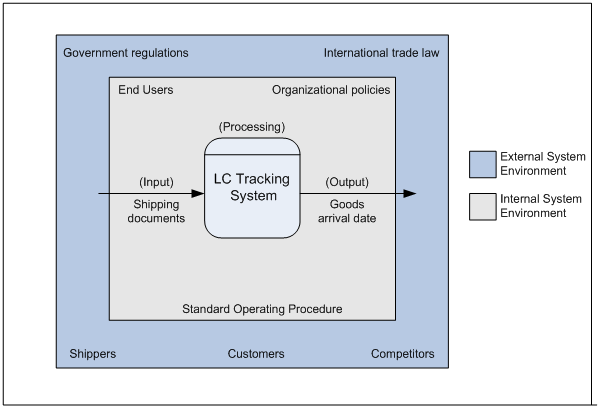
Figure 4.2: LC Tracking System as an Information System
Information systems can be either manual or automated. To analyze any information system it is necessary to break down the system into functions and components. An automated system performs the same functions as manual system but by means of information technology. Thus, in an automated system, the information system components include people, procedures, data, software, and hardware (Kroenke, 1992). The acronym PPSDH is a shorthand method of indicating system component.
4.3 Components of the Information System (PPDSH)
As mentioned earlier a information system is decomposed in the following components. In the case of LC tracking system, the following components are attributed with some specific functions.
4.3.1 People
Users:
- End-Users: End users use the system to perform their job activities (Dewitz, 1996). Customers (buyers and sellers) of the trade service department are the end-users of this system.
- Administrator: Manager or Senior Assistant officers have administrative authority in the system. He/she has the full authorization to view, edit, or to make manipulation of the data of any kind. Only the administrator has the access to the system to make necessary maintenance, make system backups for LC tracking system.
4.3.2 Procedures
The procedure implemented in the system is not a very complex one. It is necessary to have one-computer systems at the user’s premises. The user will be able to view information regarding LC’s by logging on to the internet in the respected website which will host the tracking system. The user can view his/her LC related information, make queries, track his goods from the web enabled database. He can also generate reports based on the information provided or on the queries.
4.3.3 Data
Data is the core of any Information System. The LC tracking systems deals with a variety of data. They enter and store most of the required information in the computerized system. The purpose of this system is to keep record of all the LC information categorized on buyer, seller, advising bank, negotiating bank, goods etc. All these data have to be entered and stored correctly into the system. New data have to be continuously added while others may have to be updated. Specific data have to be retrieved and used to generate reports.
4.3.4 Software
Two types of software are used to maintain the total information system.
4.3.4.1 System Software
Proposed LC Tracking System can be run on Windows 98™, Windows 2000™ and Windows XP™ environment. In case of project the system will be hosted in a windows 2000™ based operating system.
4.3.4.2 Application Software
Microsoft Access 2003™ will be used to design and to host the database of the LC Tracking System and this is also used to design the user interface to ensure the connectivity with the database.
4.3.5 Hardware
4.3.5.1 Physical Device
Computers:
This software can run on any Intel Pentium III processor with 128 MB system memory.
Printers:
Any computer printer – dot matrix, bubble jet or laser printer is able to produce printed output for the system.
5. Requirement Analysis
5.1 Requirement Analysis
Requirement Specification is an important component of the system development process. It is an essential ingredient of the system analysis phase and its proper completion ensures the success of the entire system. It is termed as the most important phase of the entire system development process. It helps the System designer to a great extent in his progress with the system development process.
It was intend to build a system for the “HSBC”. Information was gathered from the stuff of the bank. I tried to avoid any errors such as erroneousness of information required for the requirement analysis different answers for the same questions gathers from different management level etc.
5.1.1 Functional Requirements
An automated information system functions include input, processing, output, storage, control. The acronym IPOSC is a shorthand method of indicating system functions.
Input
Input functions describe the activities that must be performed to access data processing (Dewitz,1996). It is the capture of raw data from within the organization or from its external environment. In the case of opening letter of credit (LC), Import Registration Certificate (IRC), trade license, Import (IMP) form, Letter of Credit authorization (LCA) form, pro-forma invoice, credit report of the importer, credit report of seller are used. Also in the case of FOB (Freight on board), C& F (Clearing and Forwarding), insurance cover cote etc. are needed.
Processing
Processing functions describe the ways that data are manipulated to perform business functions and to produce information of value in management decision making (Dewitz,1996). In case of LC processing the processes are-
- LC application and all required document are submitted to the bank by their clients.
- Then bank verify each documents.
- Negotiate with the beneficiary/importer bank.
- Generate the LC
Output
Output functions describe the activities required to generate business documents or reports (Dewitz, 1996). The outputs of this system are the reports –
- Confirmation of LC (LC is created or not).
- Goods Shipment Information (Goods description, Shipment date, Goods quantity, Unit price, invoice value, arrival date).
- Information about the exporter (name, address, contact information, registration code)
- Advising/Negotiating bank information
The output documents are required for both the banks and also for the importer and exporter. Typical output documents for the manual LC processing are are- Bill of exchange, invoice, certificate of origin, packing list, quality control certificate.
Storage
Storage functions describe the activities required to maintain system data. Captured data must be stored in computer or storage medium in an organized manner for subsequent retrieval. As the current system (opening a LC) is not computer based, data are stored manually in the register book. But transactional data are maintained by the computers.
Control
Control functions describe the manual and automated activities performed.
- To verify the validity and accuracy of input and outputs.
- To ensure the integrity of stored data, and
- Provide data security with controlled access to data and processing information.
In the current manual system data is stored in registered books. Security measures for storing confidential information are not very high in the manual system. Any body in the department can have access to confidential information.
| People (users seller, buyer. Administrator Bank employee) | ||||
| Input | Processing | Output | Storage | Control |
People who perform input procedure administrator, user. | People who perform manual processing seller | People who perform output procedures users | people who perform storage procedure only administrator has the privilege to cerate, update and delete LC records | people who perform control procedure administrator |
| Procedure | ||||
search payment information, search invoice number, search exporter, search goods shipment, search goods location | determine goods shipment, determine loans amount, loans due date | Give reports to user | Not specified. | Security authorization as user log on to webpage and as administrator log on to the system. |
| Data | ||||
LC information | Data accessed during processing LC order quantity, invoice number, shipment date. | Report Invoice report, Payment report | LC database, payment database, exporter master file, goods database, loan master file. | sorting, add, delete, merge |
| Software | ||||
User Interface | Look up shipment information, Look up seller information, calculate shipment date, trace the shipment. | Not specified. | Microsoft Access 2000 | System Windows 2000 Professional, Windows 98. |
| Hardware | ||||
| Keyboard, Mouse | Pentium III 600 Mhz, 256 MB memory | Dot-Matrix, Inkjet, Laser Printer | Hard Disk Drive | Not specified |
Table 5.1: Function-Component Matrix of LC tracking system
5.2 Current System Analysis
Every organization has some procedures to do a job done. Procedures are sets of instructions that tell people in the organization how to perform their jobs (Dewitz, 1996). As an organization evolves, it develops standard operating procedures (SOP) to guide it operations. These procedures may be formal or informal. The formal procedures for opening a LC in the HSBC is as follows-
Bank serves it LC application form-affixing stamp, which acts as the contract between the importer and the opening bank. Then importer submits the LC application form duly signed along with IMP form (undertaking of the importer) and LCA form (authorization for opening LC). It is required to arrange margin from banker’s end. If LC is opened with 100% margin then bank collects full value of LC.
After opening of the LC, issuing bank sends telex or through SWIFT message to the advising bank located in the seller’s country to advice the LC to the beneficiary (seller). The issuing bank may also request the advising bank to confirm the credit if necessary. The advising bank advises/informs the seller that the LC has been issued. As soon as the buyers/sellers receives the LC and is satisfied that the buyer can meet the LC’s terms and conditions, then the seller is in a position to make shipment of the goods. After making shipment of goods in favor of the importer the exporter or seller submits the documents to the negotiating bank for negotiation. Negotiating bank scrutinizes the documents and if found acceptable, negotiates the documents (pays the amount to the beneficiary) and sends the said documents to the LC issuing bank. After receiving the documents, the LC issuing bank also examines the documents and if found acceptable makes payment to the negotiating bank’s account. LC opening bank request the importer to receive the documents on payment. The importer after paying all dues receives the document from the LC issuing bank and then releases the imported goods from the port authority with the help of clearing and forwarding agent.
5.3 Feasibility Study
Feasibility study determines whether the solution is feasible or achievable given the organization’s resources and constraints (Hawryszkiewycz, 1998). In order to complete this project successfully the researcher had to undergo a feasibility analysis. The researcher had to stress on three types of feasibilities-
5.3.1 Technical Feasibility
Technical feasibility is an evolution to determine whether the technology needed for the proposed system is available and how it can be integrated within the organization (Hawryszkiewycz, 1998). It refers to whether the proposed solution can be implemented with the available hardware, software and technical resources. The proposed system does not need any high configuration computer hardware and software resources. The existing facility of the bank equipped with Pentium III processors with 128 MB of memory and also windows 2000 operating systems can easily run the LC tracking system.
5.3.2 Operational Feasibility
Operational feasibility is an evolution to determine whether the system is operationally acceptable (Hawryszkiewycz, 1998). It covers two aspects. One is technical performance aspects and the other is acceptance within the organization. Technical performance includes issues such as determining whether the system can provide the right information for the organization’s performance. As the project concerned, the design and implementation of the project has been conducted such a manner so that it can provide the relevant information to the management effectively and efficiently. Operational feasibility also deals with general attitudes and skills required for the existing personnel to run the system (Hawryszkiewycz, 1998). As the project shifts the current manual process of storing LC information into a automated one, the management is technically skilled to perform such tasks. A few training sessions (two or three sessions) will hopefully be sufficient for the persons who will operate the system.
5.3.3 Economical Feasibility
This evolution looks at the financial aspects of the project. That is, it refers whether the benefit of the proposed system out-weights its costs (Hawryszkiewycz, 1998). The project does not require any financial investment. The existing technological facility is sufficient to implement the project. From the bank’s point of view it is an economically feasible project to execute.
6. Process Diagram
6.1 Process Modeling DFD Diagram
A data flow diagram (DFD) models the sources and destinations of data (external entities), the data inputs and data outputs (data flows), the actions that transforms inputs into outputs (processes), and data maintained by an information systems (data stores). There are two types of DFDs. A logical DFD models the processes that must be performed but gives no identification of how they will be performed, that is, by what person or software module. In contrast a physical DFD specifies the details of a system’s physical implementation, including who performs and how (e.g. manually or using information technology). Thus, a logical DFD describes logical functions whereas a physical DFD describes physical functions.
6.2 DFD Symbols
Data flow diagrams use four basic symbols, as represented in figure (6.1). The figure shows symbols developed by Gane and Sarson (1979). (For details see “Appendix D” )
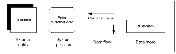
Figure 6.1: Gane and Sarson DFD Symbols
6.3 Functional decomposition and leveled DFDs
Data flow diagrams are primary modeling technique of traditional systems development because they support top-down analysis and functional decomposition. Creating leveled DFDs – multiple DFDs in which each successive level presents a more detailed view of a process – helps manage the complexity inherent in most systems and creates a model that can be viewed at many levels of process detail. Functional decomposition, as embodied in DFDs, begins with the highest level DFD, commonly called context diagram, which consolidates all processes and data stores and all internal data flows into a single process symbol representing the system. Thus, only the external entity and data flows between the system and its external entities are shown.
A Level 0 or System level DFD documents the major processes of a system, as shown in the figure 6.3. It is noticeable that, the major processes are assigned identification numbers stated as whole numbers 1, 2, 3, and so on. A 0 level DFD shows the parent processes, which may be described in more detailed in a level 1 DFD, which shows the child processes of the 0 level DFD. It is noticeable that, the level 1 processes are assigned process identification numbers plus a sequential numbering of child processes. 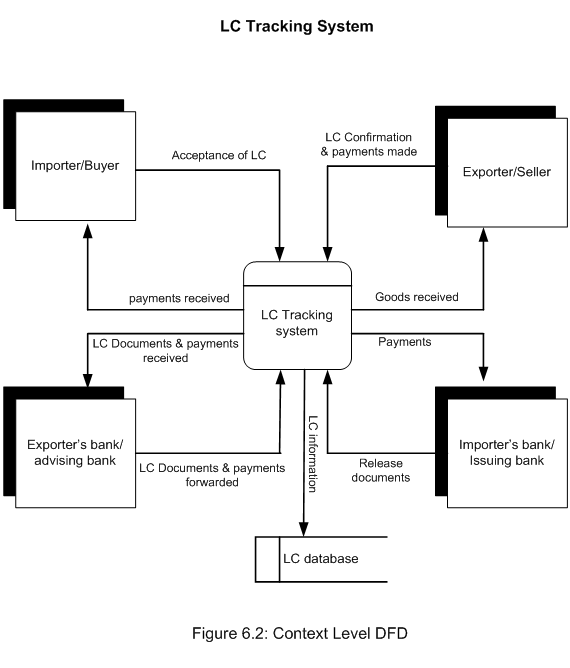
6.4 Context level DFD
Context level DFD (figure 6.2) shows the basic structure of the information flow. There are four entities. They are Importer/Buyer, Exporter/Seller, Importer’s Bank/Issuing Bank and Exporter bank/ Advising Bank. These four entities are working under one process, it is L/C tracking process. There is also a database called LC database. The information generated by this process is stored in this database. At first Importer request his Issuing Bank to open a L/C, when issuing bank accept his request and open LC then importer gives all necessary paper and documents to the issuing bank along with terms and condition. After that issuing bank sends these documents to the exporter bank. Finally exporter bank contacts with the exporter for negotiate. After negotiate exporter ship the goods and release the necessary documents and advice copy to his bank (Exporter bank). Then exporter bank inform the issuing bank that to pay and release their documents. Issuing bank inform to the importer for payment and to take the document. Importer gives the payment instruction to his issuing bank, then issuing bank sends the payment to the exporter bank and exporter bank gives the payment to the exporter.
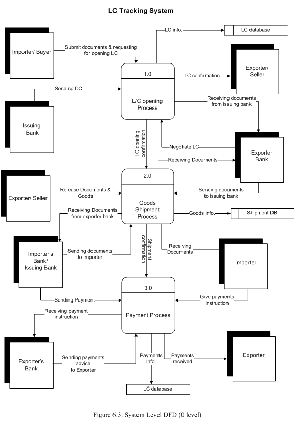
6.5 System Level Diagram
In this level, there are four entities, three process and two databases those are –
Entities
- Importer.
- Exporter.
- Issuing Bank.
- Exporter Bank.
Process
- LC Opening Process
- Goods Shipments Process
- Payments Process.
Databases
- LC Database
- Shipment Database
At first importer applies for opening a LC and submit all the necessary documents to the issuing bank. If the document meets the criteria, issuing bank accept the importer’s application and open a LC. The issuing bank keeps all the LC information in their LC database and contact with the Exporter bank and send LC papers. Exporter’s bank receives the documents and inform the exporter. Exporter Release documents, advice copy to his advising bank and ship the goods. Exporter bank sends the documents to the issuing bank. Then issuing bank informs the importer about the documents. Then importer gives payment instruction to the issuing bank. Issuing bank sends the payment to the Exporter bank and exporter bank gives the payments to the exporter.
(For more details see “Appendix D”)
7. Data Modeling
7.1 Logical Data Modeling – E-R Diagram
An important aspect of any business is record keeping. In our information society, this has become an important aspect of business, and much of the world’s computing power is dedicated to maintaining and using databases. Databases of all kinds pervade almost every business. All kinds of data, from emails and contact information to financial data and records of sales, are stored in some form of a database.
The logical data design technique most commonly used in traditional systems development is the entity-relationship (E-R) diagram. This diagram uses a number of notational conventions to model the relationship among the entities of organizations. Thus data modeling technique is based on relational database concepts.
The entity-relationship (E-R) model is a high level conceptual data model developed by Chen (1976) to facilitate database design. A conceptual data model is a set of concepts that describe the structure of the database and the associated retrieval of and update transactions on the database. The main purpose of developing a high-level data model is to support the user’s perception of the data, and to conceal the more technical aspects associated with database design. Furthermore, a conceptual data model is independent of the particular Database Management Systems (DBMS) and hardware platform that is used to implement the database.
7.2 The concepts of Entity-Relationship Model
The basic concepts of the ER model include – Entity, Relationship, and Attributes.
7.2.1 Entities
The basic concept of ER model is an entity or entity type, which represents a set of ‘objects’ in the ‘real world’ with some properties. An entity has an independent existence and can be object with a physical (real) existence or an object with an conceptual (abstract) existence. Many authors of have perceived entities in different ways – according to Bruc (1992) an entity is any distinguishable person, place, thing, event, or concept, about which information is kept. Chen (1976) noted entity as a thing which can be distinctly identified. Entities are represented as rectangle in ER diagram. In this project such entities are-
- Importer,
- Exporter,
- Importer’s bank
- Exporter’s bank
- Goods
- LC
7.2.2 Relationship
Relationships are associations between entities. Typically, a relationship is indicated by a verb connecting two or more entities. It is represented as diamond shaped.
For example
- Importer’s bank issues LC.
- Importer gives payment instruction to Issuing bank
Relationships are classified by their degree, connectivity, cardinality, direction, type, and existence. Not all modeling methodologies use all these classifications.
7.2.2.1 Degree of a Relationship
The degree of a relationship is the number of entities associated with the relationship. The n-ary relationship is the general form for degree n. Special cases are the binary, and ternary , where the degree is 2, and 3, respectively.
Binary relationships, the association between two entities is the most common type in the real world. A ternary relationship involves three entities and is used when a binary relationship is inadequate. Many modeling approaches recognize only binary relationships. Ternary or n-ary relationships are decomposed into two or more binary relationships.
7.2.2.2 Connectivity and Cardinality
The connectivity of a relationship describes the mapping of associated entity instances in the relationship. The values of connectivity are “one” or “many”. The cardinality of a relationship is the actual number of related occurrences for each of the two entities. The basic types of connectivity for relations are one-to-one, one-to-many, and many-to-many. For this particular project, only one-to-one, one-to-many relationship have been discussed as many-to-many relationship is not present in the project ER diagram.
A one-to-one (11) relationship is when at most one instance of an entity A is associated with one instance of entity B. For example, “Importer receives goods”. For each LC application there is only one consignment of goods received.
A one-to-many (1M) relationships is when for one instance of entity A, there are zero, one, or many instances of entity B, but for one instance of entity B, there is only one instance of entity A. An example of a 1 M relationships is
- One issuing bank provide loans to many applicants
- One issuing bank issues many LC
7.2.3 Attributes
The particular properties of entities are called attributes. For example, an entity in this project is Exporter. Exporter entity has some properties like Name, Address, Phone No., and Fax No. etc. The attributes of an entity hold values that describe each entity. The values held by attributes represent the main part of the data stored in the database.
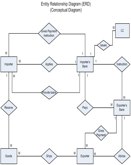
Figure 7.1: Conceptual E – R Diagram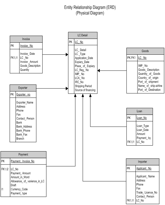
Figure 7.2: Physical E – R Diagram
7.3 Physical Data Modeling Data Dictionary
A dictionary serves as a reference or repository containing facts about the structure of data elements employed in applications. The data dictionary enables users to access and maintain the data stored in databases. The data dictionary shows the table name, data type, field size, keys, constraint and functions of the tables.
(For Data Dictionary See “Appendix E”)
8. Object Oriented Analysis
8.1 An Object Oriented Approach
The Unified Modeling Language (UML) is a graphical language for visualizing, specifying, constructing, and documenting the artifacts of a software-intensive system. UML define symbols as objects and shows the interaction, relation and inheritance among objects. UML has become a widely accepted standard for object oriented analysis. The UML offers a standard way to write a system’s blueprints, including conceptual things such as business processes and system functions as well as concrete things such as programming language statements, database schemas, and reusable software components.
8.2 Use Case Diagrams
Many object oriented analysis and design methodologies (Booch, 1994; Jacobson et al., 1992; Taylor, 1995) have adopted the concept of a use case to analyze system data structures and behaviors. A use case is a sequence of transactions in a system whose task is to yield a result of measurable value to an individual actor of the system (Jacobson et al. 1995). More simply a use case is an atomic sequence of activities that produces something of value to an external entity or a user (Dewitz, 1996). Use Case diagrams identify the functionality provided by the system (use cases), the users who interact with the system (actors), and the association between the users and the functionality. Use Cases are used in the Analysis phase of software development to articulate the high-level requirements of the system.
The primary goals of Use Case diagrams include –
- Providing a high-level view of what the system does
- Identifying the users (“actors”) of the system
- Determining areas needing human-computer interfaces
Use Cases extend beyond pictorial diagrams. In fact, text-based use case descriptions are often used to supplement diagrams, and explore use case functionality in more detail.
8.3 Graphical Notation
The basic components of Use Case diagrams are the Actor, the Use Case, and the Association.
| Actor | An Actor, as mentioned, is a user of the system, and is depicted using a stick figure. The role of the user is written beneath the icon. Actors are not limited to humans. If a system communicates with another application, and expects input or delivers output, then that application can also be considered an actor. | |
| Use Case | A Use Case is functionality provided by the system, typically described as verb+object (eg. Register Car, Delete User). Use Cases are depicted with an ellipse. The name of the use case is written within the ellipse. | |
| Association | Associations are used to link Actors with Use Cases, and indicate that an Actor participates in the Use Case in some form. Associations are depicted by a line connecting the Actor and the Use Case. |
Figure 8.1: Graphical Presentation of Use case
8.4 Use Case Analysis of LC Tracking System 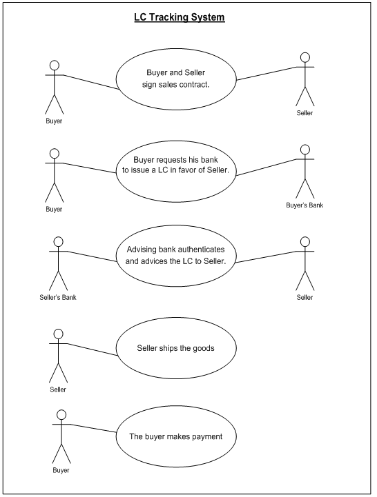
Figure 8.2: Graphical Use case analysis of L/C Tracking System
The current LC process has been decomposed in the following use cases. Each use case describes a unique process.
Use Case # 1
| Use Case Name: | Buyer and Seller sign sales contract. |
| Use Case Purpose: | Describes process of initiating trade. |
| Actors: | Buyer, Seller |
| Typical Course of Events: | |
| 1. Use case is initiated when a buyer selects a trader to buy stated amount of selected products. | |
| 2. The seller finds products offers that satisfy the request through the product, obtaining offer volumes and prices and displays these offers to the buyer. | |
| 3. If the buyer is satisfied with seller offers, request him to arrange shipment of the said amount of products. | |
| Preconditions: | |
| – Buyer desires to Buy product from the seller. | |
| – Buyer agrees to sellers offer. | |
| Alternative Courses of Actions: | |
| – At step 2 if the buyer is not satisfied with sellers offer than seller makes another offer or the buyer chooses another seller. | |
Use Case # 2
| Use Case Name: | Buyer requests his bank to issue a LC in favor of Seller. | |||||
| Use Case Purpose: | Describes the process of opening a LC | |||||
| Actors: | Buyer, Issuing bank | |||||
| Typical Course of Events: | ||||||
| 1. Buyer fills up LC application form of his bank. Providing various information required in LC application form. | ||||||
| 2. Buyer fills up letter of credit authorization form(LCA) providing information like – name, address, IRC number, renewal date, industry type, amount of LC, currency, description of products. | ||||||
| 3. The buyer fills up Form-IMP , to purchase foreign exchange for payment of imports. Information provided for this form are LCA, L/C registration number, description of goods, H.S code, I.T.C No., quantity of good-units, invoice value in foreign currency(f.o.b/c&f), country of origin, port of shipment, name of the carrier, date of shipment, intendors name and address, intendor’s registration no. | ||||||
| 4. After providing all the required information bank verifies every single form to find any discrepancies. If any discrepancy is found the form is returned to the buyer and advised to make adjustments. | ||||||
| 5. After verifying the documents the issuing bank opens a LC for the buyer and send the LC to a branch/correspondent bank in the seller’s country(advising bank) through mail, courier or by using Telex, Speedlink, SWIFT. | ||||||
| Preconditions: | ||||||
| Buyers credit reports accepted for the bank. | ||||||
| Alternative Courses of Actions: | ||||||
| At step 4 if any discrepancies found the bank ask the buyer to resolve the issue. | ||||||
Use Case # 3
| Use Case Name: | Advising bank authenticates and advices the LC to Seller. | |
| Use Case Purpose: | Describes the process of advising the LC to the Seller. | |
| Actors: | Advising bank, Seller. | |
| Typical Course of Events: | ||
| 1. This use case is initiated when the advising bank(seller’s bank) receives the LC through mail, courier, or by using Telex, Speedlink,SWIFT. | ||
| 2. The advising bank the authenticity of the LC – | ||
| a) Signatures of Issuing Bank officials on the LC verified with the specimen signatures book of the said bank when LC received by airmail. | ||
| b) If the LC is intended to be an operative cable LC(SWIFT, Telex, Speedlink), test code on the LC invariably be agreed and authenticated by two authorized officers. | ||
| c) LC scrutinized thoroughly complying with the requisites of concerned provisions. | ||
| d) Entry made in the LC advising register. | ||
| e) LC advising charges recovered. | ||
| 3. After advising bank checks the authenticity of the LC, forwards the LC to the seller. | ||
| 4. The seller receives the LC and initiates the shipment of the good. | ||
| Preconditions: | ||
| – Issuing bank opened a LC in favor of seller | ||
| – Issuing bank sent the LC to advising bank | ||
| Alternative Courses of Actions: | ||
| – At step 2(a-e) if any error or discrepancy found the LC is sent again. | ||
| – At step 3 if seller disagrees to any clause of the LC the LC is amended. | ||
Use Case # 4
| Use Case Name: | Seller ships the goods | ||
| Use Case Purpose: | Describes the process of goods shipment to the carrier. | ||
| Actors: | Seller | ||
| Typical Course of Events: | |||
| 1. The use case is initiated after the seller is advised about the LC. | |||
| 2. The goods are insured to cover the risk of any damages of the goods. | |||
| 3. Before the goods are shipped it is inspected by the custom authority to ensure the certain quality standards. | |||
| 4. The seller prepares bills of lading which ensures that the goods have been shipped on board. | |||
| 5. At the time of the shipment it is ensured that goods are uploaded on the carrier against the terms of the LC. | |||
| 6. The shipment process generates the following documents- certificate of origin, commercial invoice, Bill of exchange, insurance policy, packing list. | |||
| Preconditions: | |||
| – Seller agrees with terms and conditions provided in LC. | |||
| Alternative Courses of Actions: | |||
| – At step 3 if any discrepancy found with the quantity or quantity of the goods, the shipment is cancelled. | |||
Use Case # 5
| Use Case Name: | The buyer makes payment | |
| Use Case Purpose: | Describes process of payments | |
| Actors: | Buyer | |
| Typical Course of Events: | ||
| 1. Seller presents documents to the negotiating bank for negotiation/payment/acceptance. | ||
| 2. The negotiating bank checks documents and pays seller if documents are in order. | ||
| 3. Negotiating bank sends documents to issuing bank. | ||
| 4. Negotiating bank claims reimbursement from the issuing bank or from a bank specified in the LC. | ||
| 5. The buyer makes payment to the issuing bank after the good arrives in the port. | ||
| 6. Issuing bank delivers document to the buyer to have positions of the goods. | ||
| Preconditions: | ||
| – Seller has made the shipment of goods. | ||
| Alternative Courses of Actions: | ||
| – Not specified. | ||
8.5 Event Trace Diagram
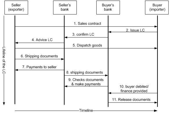
Figure 8.3: UML Event Trace Diagram
Event Trace Diagrams also known as scenario diagrams, or interaction diagram, form a powerful tool when combined with Jacobson’s use cases. An event trace diagram shows dynamic relationships among objects.
Here in the above figure the main objects are shown in the rectangle boxes above vertical lines. The horizontal lines between the vertical lines define events in the use case. These events usually result in the exchange of information between the objects. These lines closely follow the sequence portrayed by the use case. Thus the first line from seller to buyer shows the interaction of sales contract. This is followed by the request of issuing LC from the buyer to his bank. Buyers bank checks initial documents and issue LC in the favor of the seller and dispatch this to the seller’s bank. Sellers bank examines this papers and forward LC documents to the seller. This process is known as LC advising. When the seller is satisfied with the documents, he initiate shipment of the goods and handover the shipping documents to his bank. Seller’s bank pays the seller after receiving the shipping document. The seller’s bank than send these documents to buyers bank. Buyer bank checks the documents and pays to sellers bank. The buyer’s bank acknowledge the buyer receipt of shipping documents and advice the buyer to pay him and receive the documents. The buyer pays his bank and takes possession of shipping documents to release the goods from the port.
![Report on Overall activity on AB Bank ltd [part-3]](https://assignmentpoint.com/wp-content/uploads/2013/04/ab-bank2-200x100.jpg)