Generator Hardware and Accessories:
Generator Hardware and Accessories 14, 30 The sterile 99Mo/99mTc generator is a convenient source to obtain a sterile, pyrogen-free sodium pertechnetate eluate solution that is ready for intravenous administration or for aseptic preparation of [99mTc] technetium labelled radio pharmaceuticals preparations.
Essential part of the 99Mo/99mTc generator is a sterile chromatographic column of glass equipped with a glass frit near the bottom with an alumina Al2O3 absorbent on which radioactive [99Mo] molybdenum is firmly fixed after loading with Na2[99Mo]O4 (sodium molybdate) loading solution. The parent Mo-99 decays in the column and the daughter Tc-99m activity grows until its approximate the parent activity. A transient equilibrium is reached after approximately four half lives (23hrs) of the daughter Tc-99m. The chromatographic column is connected to a single needle for vacuum connection and to a double needle system meant for insertion into the saline vial for elution. The second needle is connected to an air filter for introduction of sterile air in the saline vial during elution. The column is placed in the lead pot (5cm lead thickness, weight15Kg) for the generator shielding. Additionally a bacteriological filter is installed in the suction line before the single needle to ensure the sterility of the sodium pertechnetate (Na2[99mTc]O4 )which can be eluted at regular intervals and in a very comfortable manner by using a vial containing the required volume of sterile and physiological saline and evacuated vials.
Generator hardware consists of the following accessories:
- Glass column containg alumina fixed by glass frit, rubber stoppers and Al seal.
- Single needle assembly for evacuated vial.
- Double needle assembly for physiological saline vial.
- Hydrophilic- hydrophobic Millipore (0.22µ) filter for terminal bacteriological filtration.
- Millipore (0.22µ) air filter.
- Rubber tubing for connecting hydrophobic filter with the needle systems.
- Teflon bucket for holding the needle system
- Lead pot (5cm thickness) with lead covering
- Outer hard plastic cover for protection against shock.
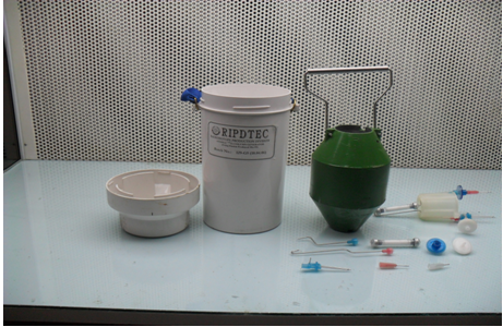
Figure-: Schematic diagram of Tc-99m generator.
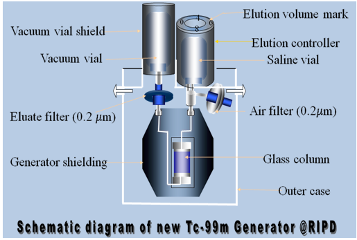
Figure-: Two generator units with stainless steel (BRIT India, Column height 7.87cm, diameter 1.66cm) and plastic outer coverings (POLATOM, Poland, Column height 7.57cm, diameter 1.0cm)
Tc-99m Generator Production Hot Cell 31-35
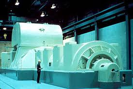
The hot cell is designed for handling 30Ci of Mo-99 in single batch. This facility is a computer controlled semi automated system developed in a joint collaboration with a German company Hans Waelischmiller Gmbh.
The Hot cell unit consists of two cells connected through an opening. The hot cell is divided into two parts-
- Mo-99 dispensing hot cell
- Generator loading hot cell
Both the cells have the inner cross dimension: – 1m length, 1m depth, and 1m height. The inner cell casing contains various opening for windows, manipulators, lighting etc. below the cell bottom there is sufficient space for waste collecting containers. The in-air and exhaust air filters including shut-off valves and connecting pipes as well as cables and other pipes are installed in the shielding space above the cell. The in-air and exhaust air is passed through HEPA filters for attaining clean room environment C inside the box.
The dispensing hot cell
The dispensing hot cell is intended for the processing of the Mo-99 solution for the generator loading process.
The box is equipped with-
Two ball tong manipulators
Steel framed lead glass window
Control desk into the front of the cell
Local dose rate meter and low pressure manometer with warning system
Double door lock for inactive material transfer and maintenance of in-cell devices
Bottom port for the transfer of bulk- radioactivity into the cell and transfer of waste
Collecting system for liquid radioactive waste
Jack hoist table adaptation to different containers
The following in-cell equipments are used in the dispensing cell:
Dose calibrator
pH-meter
Magnetic stirrer
Dispenser for small volumes
Dispensing equipment for acid, alkali, Mo-99 solution and diluents
Tubes for peristaltic pumps and accessories
Peristaltic pumps for transfer of solution
Decapper for vials
Crimper for vials
Decapper for bulk solution for plastic vials and stainless steel containers
UV-lamp
Sterile filtration unit with intermediate vessel and prick in unit
Catching device for bulk containers or vials
The loading hot cell
The loading hot cell has been installed for the Mo-99 loading to the generators.
The box is equipped with
Two ball tong manipulators
Steel framed lead glass window
Control desk into the front of the cell
Local dose rate meter and low pressure manometer with warning system
Two double door locks for the transfer of the generators
The following in-cell equipments are used in the loading cell:
Laminar flow
Tin container for solid waste
Roller conveyor for the transfer for the generator pallet
Storage for vials with loading solution with saline and evacuated vials
UV-lamp
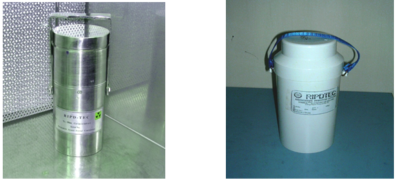
Figure-8 and 9 shows the front and rear view of Mo-99 /Tc-99m generator production hot cell at RIPD, INST, AERE.
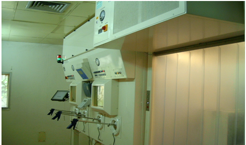
Figure-: Mo-99/Tc-99m Production Facility (HWM, Germany) with laminar flow module- [front view]
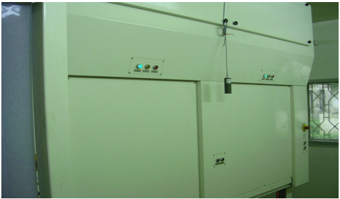
Figure-: Mo-99/Tc-99m Production Facility (HWM, Germany) – [rear view]
Cleaning and sterilization of glassware and accessories: 36
The following glassware and accessories were used for cleaning and sterilization purpose needed for the experiment. Glassware: Vials, Columns, Bottle, Volumetric flask and Beaker. Accessories: Rubber stoppers, Needles, Tubings for connection.
The glassware and the accessories were soaked in detergent and rinsed by tap water. These were then soaked in 1M HNO3 and rinsed two times with distilled water and for three times with pyrogen free water. The glasswares were sterilized at temperature 230°C in a hot air sterilizer for 1 hour. The accessories other than glasswares were steam sterilized in an autoclave at 121°C and under15psi for 30 minutes.
Preparation of physiological saline36:
The following materials were required for physiological saline preparation:
Filter assembly, Sterile membrane filter (0.22µ), Vacuum pump, Vial sealing machine, Glass jar (5L), Volumetric flask (1L), 50ml beaker, 10ml Vials, 10ml Syringe Aluminum foil, NaCl and NaNO3.
Non Pyrogenic Water collection
All the reagents needed were prepared by using pyrogen-free water, so collection of such water plays an important role in the production process. A jar of capacity 5L was used to collect water for injection. After collection this water was steam sterilized at 121 °C under15 psi.
Preparation of the isotonic NaCl solution
For 1000ml physiological saline preparation, 0.045 ± 0.005gm of NaNO3 and 9.0 ± 0.5 gm of reagent-grade sodium chloride was weighted in a 50ml glass beaker. The salt was transferred in a volumetric flask using water. 750 ml water for injection was added and the solution was stirred until complete dissolution. The volumetric flask was filled up to 1000 ml with water for injection and stirred.
Finally the pH was checked and a 10-ml filtered (0.22µ sterile filter) aliquot of the isotonic solution was tested for the absence of pyrogen. The solution was ready for further processing.
Sterilization by membrane filtration
A new and sterile membrane filter was placed in the middle part of the filter assembly. The isotonic NaCl solution was poured into upper vessel of the filtration apparatus and the apparatus was closed with a lid. The lower vessel was connected to the vacuum pump to accelerate the filtration process.
At the end of the filtration water for injection was poured on the filter membrane without disassembling the filtration apparatus in order to visually check the intactness of the filter.
Dispensing the isotonic NaCl solution and sealing the vials
The isotonic saline was dispensed into the sterile 10ml vials for elution of the of loaded generator column. The eluant vials were closed immediately after dispensing with rubber stoppers and Al seals/caps.
Steam sterilization
The closed vials were placed inside a steam sterilizer (autoclave) and autoclaved at 121°C under 15Psi for 30 minutes. After sterilization the autoclave was allowed to cool down to room temperature, vials were taken out and stored for further use.
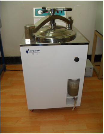
Figure-: Steam Sterilizer (JEIO TECH, Japan)
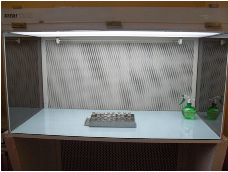
Figure-: Laminar Flow Hood (STERI, India) with Saline vials
Preparation of evacuated vials36:
The following equipment and materials were required for evacuated vial preparation:
Lyophilizer (Freeze Dryer), 10ml Vials, Rubber stoppers, Al caps, Capper machine
During the preparation of evacuated vials, the sterile rubber stoppers were placed loosely on the mouth of the sterile RS10 glass vials under laminar air flow on a tray. Then the tray with vials was put inside the evacuation chamber of the freeze dryer and evacuated down to 0.09MPa and the rubber stoppers were closed by upward movement of the lyophilizer shelves with the vials. The vials were collected and sealed with aluminum caps and subjected to vacuum and biological testing before release for use.
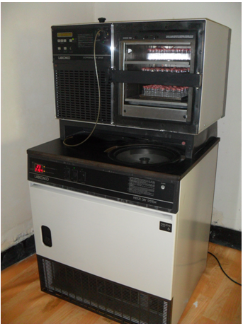
Figure-: Evacuated vial preparation in lyophilizer (LABCONCO, U. K.)
Two samples of vacuum vials were QC tested (biological) test. All the vials were tested for evacuation with Tesla gun. The evacuated vials were further used for generator elution.
Vacuum testing:
After completion of the evacuation the vials were sealed with aluminum seal and then they were taken for vacuum testing by Tesla-Gun.
Figure-: Vacuum testing by Tesla-Gun (BRINGS, Germany)
The following materials were required for chromatographic column preparation:
Alumina (Al2O3), Sieve, Beaker, HNO3, Aluminum foil, Glass column, Glass frit, Glass wool, Rubber stoppers, Al cap, Capper Machine, Tubing, Needles, Teflon needle holder.
Sieving and preparation of suspension of Al2O3
Al2O3 was sieved to the desired particle size (100-200 mesh). Al2O3 was weighted into a 100ml glass beaker for each column preparation separately. About 100ml water for injection was added and stirred. The sediment was allowed to settle for 5 minutes and the supernatant solution was decanted. These procedures were repeated for 3 times. Al2O3 was washed with pH 3-4 HNO3. The glass beakers with alumina in acid were covered with aluminum foil and were kept overnight in the LFH unit.
Filling of Al2O3 into the columns
Al2O3 of the desired particle size (100-200 mesh) was sieved and washed three times with non-pyrogenic water and the fines were discarded. pH 3-4 acid was prepared (1.6ml 1M HNO3 in 1000ml water ) and Al2O3 was washed with pH 3-4 acid and it was kept overnight covering with Al foil under the LF unit. Al2O3 having pH 3-4 was loaded in columns. Loaded columns were fixed with sintered disc, glass wool and then stoppered with rubber stopper and sealed with Al caps. After that they were set with needle and silicon glue was used at the joints to prevent any leakage. Columns were then steam sterilized and packed with Al foil for use.
Non-radioactive generator assembly
The non-radioactive generator assembly must be carried out under laminar-flow (LF) conditions of cleanliness class C in LF in order to keep the GMP conditions. The upper and lower generator needles were pricked through the upper and lower rubber stoppers of the columns, respectively. The sealed columns were set into the teflon holder with help of these needles. The connection points (needles and holder) were sealed by silicone gum. About after 1 hour the sticking paste was hardened. The free needle tips were protected with polypropylene caps. All the column assemblies were steam sterilized.
Washing of the generator columns with HNO3 of pH 3-4
The sterile loaded columns and disinfected generator hardware were assembled in laminar flow bench. The generator inlet & outlet needles were connected to the column. The vial with HNO3 of pH 3-4 was put on the generator inlet needle and the columns were washed with HNO3 of pH 3-4 to check the column packing. Unsuitable generators were rejected when the acid solution did not flow through the column or took more than 5 minutes to flow through it. The eluant was checked for Al2O3 content. The needles were protected with vials and the generators were closed with covers.
Molybdenum-99 (Mo-99):
High specific activity fission produced Mo-99 was used from authentic supplier from Indonesia/South Africa as principal raw material for production of generators. Typical lead container for Mo-99 shipment is shown in Figure-5.
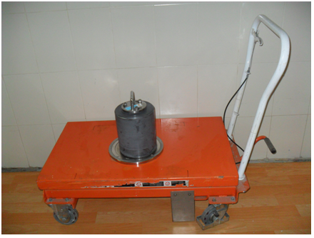
Figure-: Lead container for Mo-99 shipment on a trolley
Process Technology:
The trolley with fission Mo-99 transport container was carried to the dispensing hot cell and placed in a fixed position below bottom port of the hot cell. The lead vessel was opened and Mo-99 vial was lifted up with a gripper into the dispensing cell. The Mo-99 vial was opened by decapper and alkaline solution of Mo-99 was transferred to the mixing vessel with a peristaltic pump.
Mo-99 containing vial was washed with several times with pH 3-4 nitric acid. pH of the solution was adjusted to 3-4 using 1M HNO3 and when necessary with 0.2M NaOH. Required volume of Mo-99 solution was sucked into an intermediate glass syringe vessel. With the help of a peristaltic pump Mo-99 solution was transferred through a Millipore (0.22µ) filter to the adopter vial (Adopter vials are 20ml both sides open vials- stoppered with silicone stopper and sealed with Al cap) placed in the loading hot cell.
The preassembled sterile and apyrogenic inactive generators were placed on the transport pallet under laminar flow module and transferred into the loading hot cell. Two adopter vials were placed at the loading position for the generators under another laminar flow module inside the loading hot cell. One adopter vials contains the Mo-99 solution sucked from the dispensing hot cell and the second adopter adopted a vacuum system for loading of Mo-99 into the inactive generator column. The loading adopter was pressed on the inlet needles and the second adopter was placed on the outlet needles. The sucking process was finished when bubbles were seen in the loading adopter vial. When the generators were loaded with Mo-99 then they were taken out with trolley for experiment.
The following figure shows the schematic presentation of the computer controlled On-line Touch Screen Process Control software.
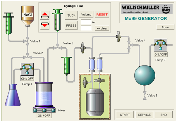
Figure-: On-lone Touch Screen Process Control Software
Elution procedure of Tc-99m Generator:
- The volume controller of the generator was adjusted for putting saline vial as requirement.
- The saline vial was pushed firmly onto the saline charge slot.
- The evacuated vial (fit in shielded holder) was pushed firmly onto the Tc-99m collection slot.
- For complete elution 1min. had to be waited.
- The Tc-99m vial was taken out (in shielded holder).
- For the next elution, the empty saline vial was taken out.
- Steps 1, 2, 3, 4 and 5 were repeated.
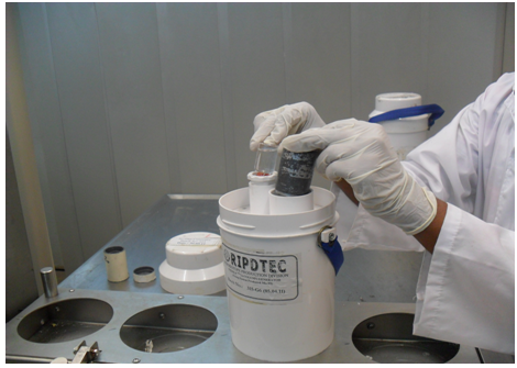
Figure-: Elution of the Tc-99m Generator with saline and evacuated vials under the LF Module
Determination of the Al2O3 bed size dependency on the elution profile of the generator
Elution Profile:
Elution profile is a graphical output of the chromatograph which shows how much radioactivity (as pertechnetate) is being carried out of the column by the eluant volume.
Elution profile reflects the radioactive concentration which can be obtained from a Tc-99m generator.
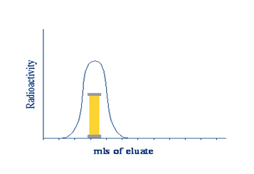
Figure-: Elution Profile
Process: In this experiment five chromatographic columns were prepared with conditioned Al2O3 of 1g, 2g, 3g, 4g and 5g respectively. These columns were loaded with Mo-99 of very small activity in the hot cell. The active generators were taken out from the hot cell for experimental work. First an elution (zero elution) with 10ml saline was taken for each generator to remove all Tc-99m. Then after 30 minutes (within this time Tc-99m activity would grow), elution was taken by using 1 ml physiological saline (0.9% NaCl). The saline vial was pressed into the inlet needles. An evacuated vial (elution vial) was placed on the outlet needle. The sucking process was finished when bubbles were seen in the elution vial. Then the vials with sodium pertechnetate solution were kept into lead shielding. The activities of Tc-99m and Mo-99 breakthrough were measured by dose calibrator. This process was repeated six times for collecting all the Tc-99m activity present. Next elutions were taken 24 hrs later. Similar procedures were carried out for all generators for several days. Elution volume vs. percentage Tc-99m activity obtained was plotted in a graph.
Measurements of Mo-99 break through for generators with optimum column bed size of alumina
Break through:
Due to imperfections in the production of the alumina column, there is always a possibility that some 99Mo is removed from the column when the generator is eluted. In a functional generator the 99Mo breakthrough should be minimal.
In order to prevent that a patient injected with large amounts of 99Mo, the generator eluate has to be checked for the presence of 99Mo.
The presence of 99Mo is assayed by measuring the 740 and 780KeV gamma rays which 99Mo emits. These gamma-energies can be separated from the 140KeV gammas emitted from the 99mTc by placing a lead shield (Mo assay canister) around the eluate, thick enough to absorb all 140KeV gamma energy emitted from Tc-99m. The dose calibrator automatically calculates Mo-99 breakthrough when the Tc-99m containg vial is placed inside the Mo-99 assay canister.
Limits:
1 MBq of 99Mo per GBq of 99mTc (Less than 0.1% European Pharmacopoeia (EP) 7, 8 ; less than 0.015% United States pharmacopoeia (USP) 5, 6
Process: For this experiment 2gm alumina bed size of twelve generators were prepared following the procedure described earlier. The height and diameter of the glass column used was 7.57cm and 1.0cm. Around 10GBq of Mo-99 was loaded sequentially in the twelve generators. Then zero hour elution was taken from generators with saline. After half an hour second elution was taken and Mo-99 break through was measured.
The Mo-99 break through (BT) is calculated by the formula =
Where ATc = Acivity of Tc-99m obtained after elution
And AMo = Acivity of Mo-99 measured in the same vial
Figure shows the Dose Calibrator with Canister for measurement of Tc-99m activity and Mo-99 break through in the eluate.
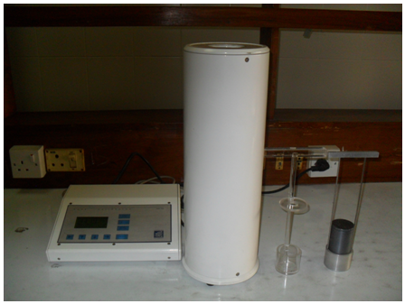 Figure-: Dose Calibrator (CAPINTECH, USA) with plastic insert and lead canister
Effect of Mo-99 loading volume on the absorption of Mo-99 on alumina based chromatographic column
For alumina (Al2O3) chromatographic columns with different bed sizes (in weight), loading volume of Mo-99 is very important. Retention of Mo-99 on alumina bed, minimum break through of Mo-99 and loss of Mo-99 from alumina bed are also important. When we loaded 1ml Mo-99 in alumina based chromatographic column, we observed that Mo-99 was adsorbed on the top surface of the alumina bed in the glass column and with increasing the loading volume of Mo-99 on the alumina bed, the area of absorbance on the alumina bed increases from top to bottom. For this reason, if we increase the loading volume of Mo-99 on alumina based column, there will be a possibility of Mo-99 loss from the column.
So our objective was to calculate the percentage of absorbance for different loading volume of Mo-99 on alumina based column keeping Mo-99 break through minimum.
Process:
For this experiment fifteen generators were prepared and were loaded with Mo-99 solution (pH 3-4) ranging from 1ml to 15ml. First the required amount of Mo-99 solution was taken in glass vials from hot cell. Then the activity of Mo-99 solution was measured by dose calibrator. The Mo-99 solutions were loaded in selected generator and sucked by vacuum vial.
After the loading some Mo-99 activity remained attached with vial wall. This activity of Mo-99 and the activity of Mo-99 (unabsorbed Mo-99 in the column) were measured by dose calibrator. Then zero hour elution was taken at once and the activity of Mo-99 the present in the zero hour elution was measured. Then the half an hour elution was taken. The activity of Tc-99m and Mo-99 were measured from this elution and the break through was measured.
Percentage of Absorbance of Mo-99 in the alumina column was calculated by the
formula =
Where A = Activity of Mo-99 taken for loading
A1 = Activity of Mo-99 left in the loading vial
A2 = Activity of unabsorbed Mo-99 in the column
A – (A1 + A2) = Total loaded activity of Mo-99 in the column