Objective:
The main purpose of the project is to maintain fluid in a desire level to any control system. PLC is used in this project as an Automation tool to reduce manual operation and get better accuracy.
Introduction:
In the past, humans were the main methods for controlling a system. More recently electricity has been used for control and early electrical control was based on relays. These relays allow power to be switched on and off without a mechanical switch. It is common to use relays to make simple logical control decisions. The development of low cost computer has brought the most recent revolution. The Programmable Logic Controller (PLC) is widely used in different plants like power generation, boiler, level control, chemical plants, textiles mills, paper plant, water treatment plant and food processing plant. Most of the present science and technology of the control system is based on microcontroller and PLC. This project work is done to present methods for designing controls software using Programmable Logic Controllers (PLC).
The advance of the PLC began in the 1970 and has become the most common choice for manufacturing controls. PLC has been gaining popularity on the factory floor and will probably remain predominant for some time to come. Most of this is because of the advantages they offer.
The PLC is not only are capable of performing the same tasks as hard-wired control, but are also capable of many more complex applications. In addition, the PLC program and electronic communication lines replace much of the interconnecting wires required by hard-wired control. Therefore, hard wiring, though still required to connect field devices, is less intensive. This also makes correcting errors and modifying the application easier. Some additional advantages of PLC are as follows:
• Smaller physical size than hard-wire solutions.
• Easier and faster to make changes.
• PLC has integrated diagnostics and override functions.
• Diagnostics are centrally available.
• Applications can be immediately documented.
• Applications can be duplicated faster and less expensively.
• Cost effective for controlling complex systems.
• Flexible and can be reapplied to control other systems quickly.
• Computational abilities allow more sophisticated control.
• Trouble shooting aids make programming easier and reduce downtime.
• Reliable components make these likely to operate for years before failure.
Basic of Programmable Logic Controller
Fundamental of PLC
A Programmable Logic Controller is a mini computer used to control equipment in an industrial facility. The kinds of equipment that PLC’s can control are as varied as industrial facilities themselves. Conveyor systems, food processing machinery, auto assembly lines…you name it and there’s probably a PLC out there controlling it. In a traditional industrial control system, all control devices are wired directly to each other according to how the system is supposed to operate. In a PLC system, however, the PLC replaces the wiring between the devices. Thus, instead of being wired directly to each other, all equipment is wired to the PLC. Then, the control program inside the PLC provides the “wiring” connection between the devices. The control program is the computer program stored in the PLC’s memory that tells the PLC what’s supposed to be going on in the system. The use of a PLC to provide the wiring connections between system devices is called soft wiring. A programmable logic controller (PLC), also referred to as a programmable controller, is the name given to a type of computer commonly used in commercial and industrial control applications. PLC differs from office computers in the types of tasks that they perform and the hardware and software they require performing these tasks. While the specific applications vary widely, all PLC monitor inputs and other variable values, make decisions based on a stored program, and control outputs to automate a process or machine.
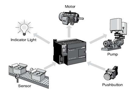
Example- Lets say that a push button is supposed to control the operation of a motor. In a traditional control system, the push button would be wired directly to the motor. In a PLC system, however, both the push button and the motor would be wired to the PLC instead. Then, the PLC’s control program would complete the electrical circuit between the two, allowing the button to control the motor.
Difference between conventional and PLC control
Conventional control system– a conventional control system consists of electromagnetic relay, timer, and switch etc. which can be used to control a specify process operation. But if any changed is required in the process then whole control system has to be changed and rewiring is needed.
Programmable logic controller– a programmable logic controller is the replacement of conventional control system such as electromechanical relays, timer, counters etc. Basically a PLC operates by examining the input signals connected from the process and carried out logic instructions on these input signals and then it produces output to a drive process, equipment or machinery. Standard interfaces uses in PLC, allow them to directly connect to the process transducers or actuators without intermediate circuitry or relay.
Basic PLC Operation
A PLC works by continually scanning a program. We can think of this scan cycle as consisting of 3 important steps. There are typically more than 3 but we can focus on the important parts and not worry about the others. Typically the others are checking the system and updating the current internal counter and timer values.
Step 1
Check input status: First the PLC takes a look at each input to determine if it is on or off other words, is the sensor connected to the first input on? How about the 2nd input? About the third. It records this data into its memory to be used during the next step.
Step 2
Execute program: Next the PLC executes program one instruction at a time. May be program said that if the first input was on then it should turn on the first output. Since it all knows which inputs are On & Off from the previous step will be able to decide whether the output should be turned on based on the state of the first input. It will store the execution result or use later during the next step.
Step 3
Update output status: Finally the PLC updates the status of the outputs. It updates the outputs based on which inputs were on during the first step and the results of executing program during the second step. Based on step 2 it would now turn on the first output because the first input was on and program said to turn on the first output when this condition is true. After the third step the PLC goes back to step 1 and repeats the steps continuously. One scan time is defined as the time it takes to execute the 3 steps listed above.
Advantages and Features of PLC
- Easy to program
- The interfacing for inputs and outputs is inside the controller.
- Does not suffer from fatigue problem
- Can be checked without field device
- Can perform complex logic operation
- Can interface with computer
- Faster system response
- Monitoring facilities available
- High reliability
- Easy to maintenance
Functional description of PLC
PLC is actually an industrial micro controller system where hardware and software specifically adapted to industrial environment. Special attention needs to be given to input and output. Because in these blocks we find protection needed in isolating a CPU blocks from damaging influences that industrial environment can bring to a CPU via input lines. Program unit is usually a computer used for writing a program
The control program can be entered into the PLC by using a simple form of high level language like ladder diagram, instruction code etc. the input device such as switch, push button, sensor and output device such as motor, relays, valves, lamps etc. are connected to PLC. The operator then enters a sequence of instructions into the memory of the PLC. The controller then monitors the inputs and outputs according to these programs and carries out the control rules for which it has been programmed.
Power supply- electrical supply is used in bringing electrical energy to central processing unit. Most PLC controllers work either at 24 VDC or 220 VAC. In some PLC controllers are electrical supply as a separate module. Those are usually bigger PLC controllers, while small and medium varies already contain the supply module, user has to determine how much current to take from 0
Basics of Manual and Automatic Control
Manual control- when the operator to operate the process to a desired condition, then it carries out the corrective action is said to be manual control. The operator adjusts the output to operate the plant. During start-up, this mode is normally used.
Automatic control
When the instruments carry out the corrective action, then it is automatic control.
Advantage of Automatic control
- Increase production
- Improve quality
- Greater production uniformity
- Saving in raw materials
- Saving in manpower
Conventional control system & PLC
Conventional control- a conventional control system consists of electromagnetic relay,
Use of PLC instead of conventional procedure
PLC not only are capable of performing the same tasks as hard-wired control, but are also capable of many more complex applications. In addition, the PLC program and electronic communication lines replace much of the interconnecting wires required by hard-wired control. Therefore, hard wiring, though still required to connect field devices, is less intensive. This also makes correcting errors and modifying the application easier. Some of the additional advantages of PLC are as follows:
• Smaller physical size than hard-wire solutions.
• Easier and faster to make changes.
• PLC has integrated diagnostics and override functions.
• Diagnostics are centrally available.
• Applications can be immediately documented.
• Applications can be duplicated faster and less expensively.
The soft wiring advantage provided by programmable controllers is tremendous. In fact, it is one of the most important features of PLC’s. Soft wiring makes changes in the control system easy and cheap. If you want a device in a PLC system to behave differently or to control a different process element, all you have to do is change the control program. In a traditional system, making this type of change would involve physically changing the wiring between the devices, a costly and time-consuming endeavour. Let’s say that two push buttons, PB1 and PB2, are connected to a PLC. Two pilot lights, PL1 and PL2, are also connected to the PLC. The way these devices are connected now pressing push button PB1 turns on pilot light PL1 and pressing push button PB2 turns on pilot light PL2. Let’s say that you want to change this around so that PB1 controls PL2 and PB2 controls PL1. In a traditional system, you would have to rewire the circuit so that the wiring from the first push button goes to the second pilot light and vice versa. However, because these devices are connected to a PLC, making this change is as simple as making a small change in the control program. In addition to the programming flexibility we just mentioned, PLC’s offer other advantages over traditional control systems. These advantages include:
• High reliability
• Small space requirements
• Computing capabilities
• Reduced costs
• Ability to withstand harsh environments
• Expandability
PLC components and operation
The basic elements of a PLC include input modules or points, a central processing unit (CPU), output modules or points, and a programming device. The type of input modules or points used by a PLC depends upon the types of input devices used. Some input modules or points respond to digital inputs, also called discrete inputs, which are either on or off. Other modules or inputs respond to analog signals. These analog signals represent machine or process conditions as a range of voltage or current values. The primary function of a PLC’s input circuitry is to convert the signals provided by these various switches and sensors into logic signals that can be used by the CPU.
The CPU evaluates the status of inputs, outputs, and other variables as it executes a stored program. The CPU then sends signals to update the status of outputs. Output modules convert control signals from the CPU into digital or analog values that can be used to control various output devices. The programming device is used to enter or change the PLC’s program or to monitor or change stored values. Once entered, the program and associated variables are stored in the CPU. In addition to these basic elements, a PLC system may also incorporate an operator interface device to simplify monitoring of the machine or process.
The Central Processing Unit
The central processing unit (CPU) is the part of a programmable controller that retrieves, decodes, stores, and processes information. It also executes the control program stored in the PLC’s memory. In essence, the CPU is the “brains” of a programmable controller. It functions much the same way the CPU of a regular computer does, except that it uses special instructions and coding to perform its functions.
The CPU has three parts:
• The processor
• The memory system
• The power supply
The processor is the section of the CPU that codes, decodes, and computes data. The memory system is the section of the CPU that stores both the control program and data from the equipment connected to the PLC. The power supply is the section that provides the PLC with the voltage and current it needs to operate.
The control program
The control program is a software program in the PLC’s memory. It’s what puts the control in a programmable controller. The user or the system designer is usually the one who develops the control program. The control program is made up of things called instructions. Instructions are, in essence, little computer codes that make the inputs and outputs do what you want in order to get the result you need. There are all different kinds of instructions and they can make a PLC do just about anything (add and subtract data, time and count events, compare information, etc.). All you have to do is program the instructions in the proper order and make sure that they are telling the right devices what to do and voila…you have a PLC-controlled system. And remember, changing the system is a snap. If you want the system to act differently, just change the instructions in the control program. Different PLC offer different kinds of instructions. That’s part of what makes each type of PLC unique. However, all PLC use two basic types of instructions:
• Contacts
• Coils
Contacts- Contacts are instructions that refer to the input conditions to the control program that is, to the information supplied by the input field devices. Each contact in the control program monitors a certain field device. The contact waits for the input to do something in particular (e.g., turn on, turn off, etc.—this all depends on what type of contact it is). Then, the contact tells the PLC’s control program, “The input device just did what it’s supposed to do. You’d better check to see if this is supposed to affect any of the output devices.”Coils- Coils are instructions that refer to the outputs of the control program that is, to what each particular output device is supposed to do in the system. Like a contact, each coil also monitors a certain field device. However, unlike a contact, which monitors the field device and then tells the PLC what to do, a coil monitors the PLC control program and then tells the field device what to do. It tells the output device, “Hey, the PLC just told me that the switch turned on. That means that you’re supposed to turn on now. So let’s go!”
Example- Let’s talk again about that soaped-up switching circuit, in which a wall switch and an overhead light are connected to a PLC. Let’s say that Turning on the switch is supposed to turn on the light. In this situation, the PLC’s control program would contain a contact that examines the input device the wall switch for an on condition and a coil that references the light. When the switch turns on, the contact will energize, meaning that it will tell the PLC that the condition it’s been looking for has happened. The PLC will relay this information to the coil instruction by energizing it. This will let the coil know that it needs to tell its referenced output the light to turn on.
In PLC talk, this three-step process of monitoring the inputs, executing the PLC control program, and changing the status of the outputs accordingly is called the scan.
Inputs monitor→ program execute→ Change outputs scan
Chapter: 2
Project implementation
Project Diagram
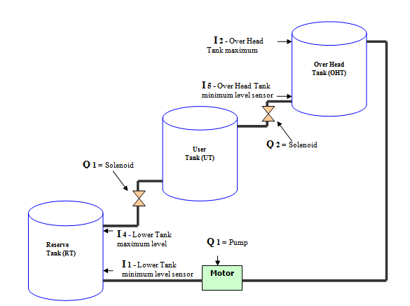
Diagram of the overall project
Input:
I1 → Lower Tank minimum level indicator sensor
I2 → Over Head Tank maximum level indicator sensor
I3 → System Switch
I4 → Lower Tank maximum level indicator sensor
I5 → Over Head Tank minimum level indicator sensor
Output:
Q1 → Pump (Motor)
Q2 → Solenoid Valve (for middle tank)
Q3 → Solenoid Valve (for reserve tank)
Q4 → System Relay
Working Principles
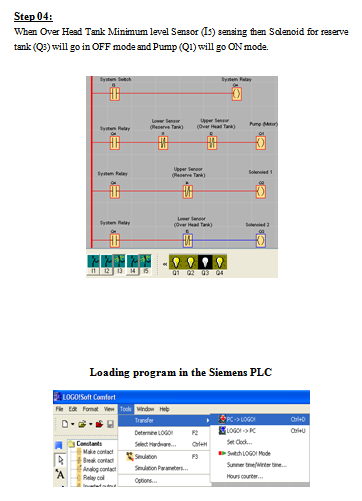
- When the system switch I3 is ‘ON’ the Over all systems ‘ON’.
- When the fluid level in overhead tank decreases and the sensor I5 indicate the minimum level. The Pump will go in START mode. The fluid will go in to the overhead tank and both solenoid Q2 and Q3 (for middle tank and reserve tank) will go in OFF mode.
- When the fluid level in overhead tank increases and the sensor I2 indicate the maximum level. The Pump will go in OFF mode and both solenoid Q2 and Q3 (for middle tank and reserve tank) will go in ON mode. The fluid will flow down in to the Middle tank.
- When the fluid level of the lower tank rises up and the sensor I4 indicate the maximum level. Both solenoids Q2 and Q3 will go in OFF mode and the pump will go in START mode. The fluid will go in to the overhead tank again
- The cycle will be continued
Solenoid:
A solenoid valve is an electromechanical actuator to control fluid flow. A solenoid valve has two main parts: the solenoid and the valve The valve is controlled by an electrical signal through a solenoid coil.. The solenoid uses electrical signal and provides the mechanical work, which in turn, opens or closes the valve mechanically.
Sensor:
Sensors are the sensing and controlling output.
Mounting of the weight sensor:
There are two weight sensor used in the overhead tank and the lower tank. This two sensor gives the input signals (I1, I2, I4 , I5) as stated above.
Mounting of switch:
Use wires: Current use: 16 (4) Amp. 250 V
BLACK and BLUE
With these contacts the regulator closes when up opens when down.
BROWN and BLACK
With these contacts the regulator closes when down opens when up.
Control Penal
Logic diagram (program)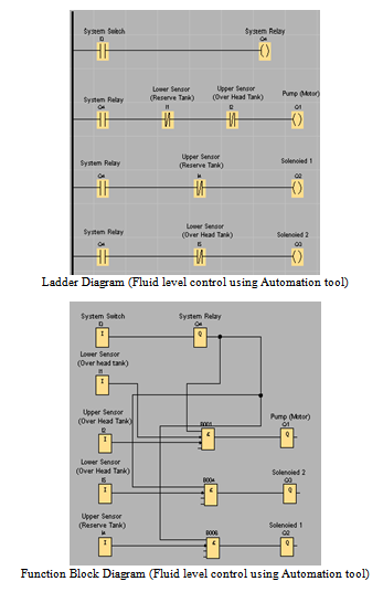
LOGO! Soft Comfort V5.0
Chapter: 3
Process control system
Process control system
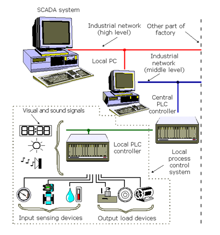
A process control system is made up of a group of electronic devices that provide stability, accuracy and eliminate harmful transition statuses in production processes. Operating systems can have different arrangements and implementation; from energy supply units to machines. As technology quickly progresses, many complex operational tasks have been solved by connecting programmable logic controllers and a central computer. Beside connections with devices (e.g., operating panels, motors, sensors, switches, valves, etc.) possibilities for communication among instruments are so great that they allow a high level of exploitation and process coordination. In addition, there is greater flexibility in realizing a process control system. Each component of a process control system plays an important role, regardless of its size. For example, without a sensor, the PLC wouldn’t know what is going on during a process. In an automated system, a PLC controller is usually the central part of a process control system. With the execution of a program stored in program memory, PLC continuously monitors status of the system through signals from input devices. Based on the logic implemented in the program, PLC determines which actions need to be executed with output instruments. To run more complex processes it is possible to connect more PLC controllers to a central computer. A system could look like the one pictured below:
Conventional control panel
At the outset of industrial revolution, especially during sixties and seventies, relays were used to operate automated machines, and these were interconnected using wires inside the control panel. In some cases a control panel covered an entire wall. To discover an error in the system much time was needed especially with more complex process control systems. On top of everything, a lifetime of relay contacts was limited, so some relays had to be replaced. If replacement was required, machine had to be stopped and production too. Also, it could happen that there was not enough room for necessary changes. control panel was used only for one particular process, and it wasn’t easy to adapt to the requirements of a new system. As far as maintenance, electricians had to be very skillful in finding errors. In short, conventional control panels proved to be very inflexible. Typical example of conventional control panel is
given in the following picture.
In this photo you can notice a large number of electrical wires, time relays, timers and other elements of automation typical for that period. Pictured control panel is not one of the more “complicated” ones, so you can imagine what complex ones looked like. Most frequently mentioned disadvantages of a classic control panel are:
– Too much work required in connecting wires
– Difficulty with changes or replacements
– Difficulty in finding errors; requiring skillful work force
– When a problem occurs, hold-up time is indefinite, usually long.
Control panel with a PLC controller
With invention of programmable controllers, much has changed in how a process control system is designed. Many advantages appeared. Typical example of control panel with a PLC controller is given in the following picture.
Advantages of control panel that is based on a PLC controller can be presented in few basic points:
1. Compared to a conventional process control system, number of wires needed for
connections is reduced by 80%
2. Consumption is greatly reduced because a PLC consumes less than a bunch of relays
3. Diagnostic functions of a PLC controller allow for fast and easy error detection.
4. Change in operating sequence or application of a PLC controller to a different operating process can easily be accomplished by replacing a program through a console or using a PC software (not requiring changes in wiring, unless addition of
some input or output device is required).
5. Needs fewer spare parts
6. It is much cheaper compared to a conventional system, especially in cases where a large number of I/O instruments are needed and when operational functions are complex.
7. Reliability of a PLC is greater than that of an electro-mechanical relay or a timer.
Systematic approach in designing an process control system
First, you need to select an instrument or a system that you wish to control. Automated system can be a machine or a process and can also be called an process control system. Function of an process control system is constantly watched by input devices (sensors) that give signals to a PLC controller. In response to this, PLC controller sends a signal to external output devices (operative instruments) that actually control how system functions in an assigned manner (for simplification it is recommended that you draw a block diagram of operations’ flow).
Secondly, you need to specify all input and output instruments that will be connected to a PLC controller. Input devices are various switches, sensors and such. Output devices can be solenoids, electromagnetic valves, motors, relays, magnetic starters as well as instruments for sound and light signalisation. Following an identification of all input and output instruments, corresponding designations are assigned to input and output lines of a PLC controller. Allotment of these designations is in fact an allocation of inputs and outputs on a PLC controller which correspond to inputs and outputs of a system being designed.
Third, make a ladder diagram for a program by following the sequence of operations that was determined in the first step.
Finally, program is entered into the PLC controller memory. When finished with programming, check up is done for any existing errors in a program code (using functions for diagnostics) and, if possible, an entire operation is simulated. Before this system is started, you need to check once again whether all input and output instruments are connected to correct inputs or outputs. By bringing supply in, system starts working.
Chapter: 4
Competence
Program support
Programming only related examples make up the first group of examples. They are given as separate small programs that can later be incorporated into larger ones. Second group consists of examples, which can be applied to some real problems.
Self-maintenance
Program allows input to remain at ON status even when the condition that brought it to that status stops. Example in picture below illustrates how use of a key connected to the input IR000.00 changes IR010.01 output status to ON. By letting the key go, output IR010.01 is not reset. This is because IR010.01 output keeps itself at status ON through OR circuit (having IR000.00), and it stays in this status until key at input IR000.01 is pressed. Input IR000.01 is in I connection with the output pin IR010.01 that cancels out a condition, and resets an IR010.01 bit. Example of self-maintenance is quite frequent in specific applications. If a user was connected to IR010.01 output, START and STOP functions could be realized from two keys (without the use of switches). Specifically, input IR000.00 would be a START key, and IR000.01 would be a STOP key.
Making large time intervalsIf it’s necessary to make a bigger time interval of 999.9 seconds (9999×0.1s) two linked timers, or a timer and a counter can be used as in this example. Counter is set to count to 2000, and timer is set to 5 seconds, which gives a time interval of 10.000 seconds or 2.77 hours. By executing a condition at IR000.00 input, timer begins to count. When it reaches the limit, it sets a flag TIM001 that interrupts the link and simultaneously resets a timer. Once 5 seconds have run out, flag TIM001 changes its status to ON and executes a condition at the counter input CNT002. When a counter numbers 2000 such changes in timer flag status, TIM001 sets its flag CNT002 which in turn executes a condition for IR010.00 to change status to ON. Time that has elapsed from the change of IR000.00 input status to ON and a change of IR010.00 input status to ON come to 10.000 seconds.
Delays of ON and OFF status
Example shows how to make output (IR010.00) delay as opposed to? (In relation to? unclear meaning) input (IR000.00). By executing a condition at IR000.00 input, timer TIM000 begins counting a set value 10 in steps of 0.1 seconds each. After one second has elapsed, it set its flag TIM000 that is a condition in changing output status IR010.00 to ON. Thus we accomplish a delay of one second between ON status of IR000.00 input and ON status IR010.00 input. By changing IR010.00 output status to ON, half of the condition for activation of the second timer is executed. Second half of the timer is executed when IR000.00 input changes status to OFF (normally closed contact). Timer TIM001 sets its flag TIM001 after one second, and interrupts a condition for keeping an output in ON status.
Counter over 9999
If you need to count over 9999 (maximum value for a counter), you can use two connected timers. First counter counts up to certain value, and the other one counts flag status changes of the first counter. Thus you get the possibility of counting up to a value that is a result of set values of the first and second counter. In an example at the bottom, first counter counts up to 1000, and second up to 20 which allows you to count to 20000. By executing a condition at IR000.00 input (line whose changes are followed is brought to it), first counter decreases its value by one. This is repeated until counter arrives at zero when it sets its flag CNT001 and simultaneously resets itself (is made ready for a new cycle of counting from 1000 to 0). Each setting of CNT001 influences the other counter which sets its flag after twenty settings of the first counter’s flag. By setting CNT002 flag of the second counter, a condition is executed for an IR010.00 output to be activated and to stay in that status through self-maintenance.
Same effect can be achieved with a modified program below. First change is that there is a “switch” for the whole program, and this is IR000.00 input (program can accomplish its function only while this switch is active). Second change is that the line whose status is followed is brought to IR000.01 input. The rest is the same as in the previous version of the program. Counter CNT002 counts status changes of the CNT001 counter flag. When it numbers them, it changes the status of its flag CNT002 that executes the condition for status change of IR010.00 output. This changes IR010.00 output status after 20000 changes of input IR000.01.
Alternate ON-OFF output
Example makes a certain number of impulses of desired duration at PLC controller IR010.00 output. Number of impulses is given in instruction of the counter (here it is a constant #0010 or ten impulses) impulse duration in two-timer instructions. First timer defines duration of ON status, and second one duration of OFF status of IR010.00 output bit. In the example these two durations are the same, but through assigning them different parameters they can differ so that duration of ON status can be different from duration of OFF status.Program starts executing a condition at IR000.00 bit. Since a normally closed contact which refers to counter flag (that isn’t set ) is linked with this IR000.00 bit in “I” circuit, this status of IR200.00 bit will change to ON. Bit IR200.00 keeps its status through self-maintenance until counter flag is not set and a condition interrupted. When an IR200.00 bit is set, timers TIM001 and TIM002 start counting a set interval number at 0.1 s ( in the example, this number is 10 for the first timer, or 20 for the second timer, and this sets the period of one or two seconds). With both timers, a normally closed contact which refers to TIM002 timer flag is connected with IR200.00 bit. When this flag is set which happens every two seconds, both timers are reset. Timer TIM002 resets timer TIM001 and itself, and this starts a new cycle. At the start of a program, IR010.00 output bit changes status to ON and stays in this status until TIM001 flag changes status to ON (after one second). By changing TIM001 flag status to ON, condition is broken (because it is represented as normally closed contact) and IR010.00 bit changes status to OFF. IR010.00 output status changes to ON again when time has run out on TIM002 timer. This resets TIM001 timer and its flag, which in turn executes a condition for status change of the IR010.00 output. Cycle is thus repeated until a counter numbers 10 changes of TIM001 flag status. With the change of status of CNT000 counter flag, a condition for an assisting bit IR200.00 is broken, and program stops working.
Application of this project
Fluid level control in BTS station
Water level control in Boiler
Gasoline level control in any types of fuel station
Generator and Automotive engine
Chemical level control in washing plant
Homely use water tank level
Water treatment plant
It also can use in arithmetic functions of different process and modern industries like pharmaceuticals, Fertilizer, Power station, Cement factory, packaging and so on.
Conclusion and Discussion
It has been a great pleasure to work on practice & progress of PLC based fluid level control system. It provides information about many topics relevant to controlling system or equipment automation. We have more learned about the fuel & water level control system. It can run automatically by the help of PLC. The great advantage of PLC based fuel & water level control system is with maximum accuracy. Also the system has higher reliability, small space requirements reduced cost and able to work as friendly with environment.
Further Recommendation
In this project we used Programmable Logic Controller as Automation Tool. It’s a combination of solid state device to perform specific task using Ladder logic. It may easily run a control system with more system accuracy, smoothly and efficiently. In other hand- we can control this system by Microcontroller instead of Programmable Logic Controller. As an automation tool Microcontroller is efficient enough to control this project. It will make this project perfect and success in many ways-
Firstly, we can make this project in less cost and due to its high expenses it is not a good idea in mass production. Secondly, it required less space then Programmable Logic Controller. Thirdly, PLC cannot handle complex situation. That’s why, now a days- Microcontroller is used thoroughly in process control, control of machinery, Factory assembly line, Upgrade automotive Vehicle also…
In future we hope that, the Fluid Level Control will be designed by Microcontroller Instead of Programmable Logic Controller.