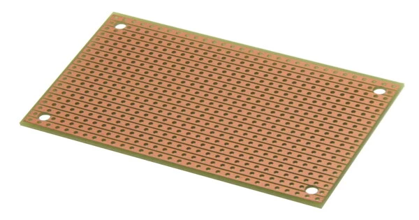
Stripboard is the generic term for a popular type of electronics prototyping material for circuit boards that is distinguished by a pre-formed 0.1 inch (2.54 mm) regular (rectangular) grid of holes, with wide parallel strips of copper cladding running in one direction all the way across one side of an insulating bonded paper board. It is a type of electronic prototyping board. It is made up of a thin, flat insulating board (typically fiberglass) with a series of parallel copper strips or pads running across it. It is also commonly known as Veroboard, which is a trademark of British company Vero Technologies Ltd and Canadian company Pixel Print Ltd in the United Kingdom.
These copper strips are typically arranged in a grid pattern, with holes drilled at regular intervals along the strips through the board. The Electronics Department of Vero Precision Engineering Ltd (VPE) invented and developed it in the early 1960s. It was introduced as a general-purpose material for use in the construction of electronic circuits, distinguishing itself from purpose-designed printed circuit boards (PCBs) in that a wide range of electronics circuits can be built using a standard wiring board.
Breaks are made in the tracks, usually around holes, to divide the strips into multiple electrical nodes when using the board. Breaking between holes with care allows for components with two pin rows only one position apart, such as twin row headers for IDCs.
Stripboard is frequently used to build electronic circuits and solder components to the board. The copper strips connect the components electrically, and the holes allow for through-hole soldering. You can create custom tracks and connections to match your circuit design by cutting and shaping the copper strips.
To use stripboard, you would typically follow these steps:
- Plan your circuit: Design your circuit on paper or using a computer-aided design (CAD) software. Identify the components and their connections.
- Prepare the stripboard: Cut the stripboard to the desired size for your circuit. Stripboard usually comes in various sizes, and you can cut it using a saw or a sharp knife. Make sure to wear appropriate safety gear when cutting the board.
- Mark component placements: Using a marker or a pencil, mark the positions of the components on the stripboard according to your circuit design. This step helps you visualize the layout and avoid mistakes during assembly.
- Insert and bend component leads: Insert the components into the stripboard, aligning the component leads with the marked positions. Bend the component leads at a right angle to hold them in place.
- Create connections: Use a wire cutter/stripper to cut and strip solid-core wires to the desired length. Insert one end of a wire into a component lead and bend it to make contact with an adjacent copper strip or hole.
- Test and troubleshoot: Once you have soldered all the connections, double-check your circuit for any mistakes or loose connections. Use a multimeter or other testing equipment to verify the functionality of your circuit.
Stripboard is not designed for surface-mount components, but many such components can be mounted on the track side, especially if tracks are cut/shaped with a knife or small cutting disc in a rotary tool.