The fears of climate change increase, the demands for devices that generate electricity that are environmentally friendly will steadily increase. Most of the electric power generated in the world comes from the burning of fossil fuels to generate a consistent supply of energy. Every year, the demand for electricity increases, pushing the current power plants and power distribution grids to their limits. To meet this growing need, more fossil fuel power plants are being constructed, thus increasing the pollutants dispensed into the environment. The need to develop clean energy-producing systems that can perform as reliably as fossil fuel plants must be implemented throughout the world in order to decrease the effects man has on the planet. In order for a renewable energy source to be added to a power utility, the three conditions to be met are reliability, cost, and lifespan. Due to the high initial cost of building a renewable power source and slower rate of return than fossil fuel plants, progress has been slow in the construction of renewable energy plants outside of wind power plants. The design of this project focuses on using a renewable-energy-based stand-alone system to decrease the energy usage at times of low power consumption and promotes the use of an environmentally friendly energy resource. There are many forms of renewable energy resources that are currently available for integration into the power grid; the top four energy sources are wind, sun, water, and geothermal.
1.2. FOUR MAIN RENEWABLE ENERGY FORMS
The main types of renewable energy are wind energy, solar photovoltaic, hydroelectric, and geothermal. Every year, the demand for electricity grows. To meet this increased demand, countries have to decide what form of generation will provide reliable power that will fulfill the future needs of the people. The public demand for the integration of renewable energy grows with every study on climate change. Fossil fuel power plants deliver the necessary electricity that can be raised or lowered to meet the demand, but produce byproducts that are harmful to the environment. The oldest forms of renewable energy that harness the power of nature are wind turbines and hydroelectric power plants. Both forms have been used for hundreds of years to improve the quality of life for the people by using machines powered by nature. Photovoltaic energy has only been around a few decades, and came about through advancements in the space program. The performances of the individual cells of a solar panel are steadily improving with newer advancements with semiconductor material.
1.3. WIND ENERGY
Converting the movement of air into electricity is the fastest growing supplier of renewable energy in Europe. Wind farms produce massive amounts of power that provide an environmentally friendly option to counteract the growing need for more fossil fuel plants. The drawbacks that hinder the expansion of wind turbines are the distance from turbines to the power grid, startup cost, inconsistency of wind speed, and visual aesthetics. Areas in the U.S. that generate the most air flow are in remote locations that require running power lines hundreds of miles to reach the power grid from wind farms located 10 kilometers from shore, in isolated locations surrounded by farm land, and at the edges of mountain ranges. The slope of mountain ranges produces higher wind speeds than any coastline, as shown in Figure 1.
Figure 1.1. Demonstrates that most of the regions capable of producing sustainable airflow are located far from large urban centers. The Northeast and the West coast of the United States produce the air speeds capable of providing adequate airflow to generate continuous electricity from offshore wind farms. The shore lines that work well for wind generation are located in areas where people perceive the wind turbines as obstructions that are visually intrusive and spoil the natural beauty that draws tourists. For wind energy to become a practical energy source that can meet the demands of the public, the issue of reliability must be resolved to meet the varying loads that occur throughout the day.
1.4. GEOTHERMAL
One of the largest-producing sources of renewable energy in the world is geothermal. All other forms of renewable energy in one form or another harness their energy from the sun; geothermal plants harness the energy of the planet The formation of magma below the surface of the Earth provides energy that is harvested to produce power. Geothermal power plants generate electricity through means of capturing hot water or steam from the ground, which drives a turbine. The combined output of solar and wind energy make up less than half the power produced using geothermal energy. Compared with wind and solar energy, the cost per kilowatt-hour is much less for geothermal; in some regions, the cost of fossil fuel plants are higher. The Southwest generates the majority of the geothermal capabilities of the United States. The Philippines, El Salvador, Nicaragua, and Iceland have the highest percentages for incorporating geothermal energy into their power generation capabilities the advantage of geothermal energy is that the fuel source is constant and produces little in the way of harmful byproducts. The planet naturally produces the energy harnessed, but the lifespan for power generation is dependant on the time period it takes for the magma to cool ranging from five thousand to one million years. The main drawback of geothermal power is that the output gases in confined spaces are hazardous and there is potential for ground subsidence.
1.5. HYDROELECTRIC
Harnessing the power of water is the oldest form of renewable energy. Hydroelectric power provides a fifth of the world’s electricity and is the main source of power for dozens of countries around the world. The generation equipment in a hydroelectric plant is similar to plants that burn fossil fuels to produce steam for powering their generators. The conversion of water to steam in a coal plant produces byproducts that pollute the environment. Hydroelectric plants harness the kinetic energy of flowing water instead of steam to spin the generator turbines. There are multiple ways to harness the power of water, such as building dams or altering the flow of a river. The largest power producers are dams, which block the flow of a river to store millions of gallons of water to create an endless supply of fuel for the generators. A dam works on the principle of water pressure; the higher the water level, the farther the water will fall. The water gains speed from gravity and, in turn, pass the energy off to the rotor that spins the turbine to generate power. In regions incapable of building a dam, the next hydroelectric power plant harnesses the kinetic energy of a fast- moving river by diverting the water through a tunnel to spin the turbine shaft. This form is less reliable than a dam due to fluctuations in river levels, but has a lower startup cost and does not block passage of the river. The form of is similar to a dam, except that the water is pumped into the basin. During off-peak hours, the water is pumped from a river or lake to the holding reservoir to be used during hours of high demand. The main benefits of using hydroelectric facilities is the ability of the plant to increase or decrease the power output fairly quickly, minuscule fuel cost, multiple decade life spans, consistent water flow, and increased reliability compared with the other renewable energy producers. The drawbacks are the initial cost of construction, the difficulty in locating an acceptable location to build a facility, the effect on local wildlife, the flooding of hundreds of acres of land, and affecting the downstream environment’s water quality and quantity.
1.6. SOLAR PHOTOVOLTAIC
The most abundant fuel source in the realm of renewable energy is the sun. Solar panels produce electricity through individual photovoltaic cells connected in series. This form of energy collection is viable in regions of the world where the sun is plentiful, and can be used in isolated regions or on houses to supplement the rising cost of electricity from a power grid. To convert the sun’s energy, the cells capture photons to create freed electrons that flow across the cells to produce usable current. The efficiency of the panel is determined by the semiconductor material that the cells are made from as well as the process used to construct the cells. Solar panels come in three types: amorphous, monocrystalline, and polycrystalline. The more efficient the material the panel is constructed from, the greater the cost. To maximize results, there are many features that can be used to control the output of the photovoltaic panels. The power needs determine what components are used to produce the desired voltage and current for the project such as converters, solar trackers, and the size of the panel. Converters transform the variable output from solar panels to constant voltages to maximize the continuous supply of usable power for either present needs or stored for future use. The output power of the panel is affected by many variables that continually change throughout the day. This produces fluctuations in voltage and current that makes the panel inefficient unless the outputs are constantly adjusted to maximize the power output. The oscillating conditions are determined by environmental factors, chemical composition of the panel, and the angular position of the sun. Since solar energy is only produced during the day, requiring an energy storage application by either a battery or connecting to the power grid to provide power during the night
1.7. WEATHER AND SOLAR ENERGY
Many factors contribute to the maximization of the output power of solar panels include cloud cover, temperature, and the angle of the sun. Changing seasons complicate the design of the solar system, since all factors are constantly varying. The light intensity is less in the winter months than in the summer due to the differences in the sun’s height at the summer and winter solstice. During the year, the sun moves between its highest apex in the sky at the beginning of the summer and its lowest at the beginning of winter. The angle at which the panels are placed on their mounts determines how much energy is collected and how much is reflected off the surface. Most structures use fixed- angle mounts that are positioned for either a specific season or a midpoint to average the summer and winter outputs. Increasing the number of hours a panel generates at peak efficiency entails the use of a power tracker to follow the sun across the sky. This system tracks the sun and adjusts the angle of the panel to allow the cells to capture more photons than a fixed-position mount. The panel on the power tracker generates more current in the morning and evening hours, increasing the number of hours the panel will gain maximum energy. Temperature variations have a noticeable effect on photovoltaic cells. As the temperature increases, the efficiency of the panel decreases, but, at the same time, temperature coincides with higher levels of illumination . Figure 2. shows that increasing temperature decreases the voltage, compared with the output current under the same conditions. Weather determines the amount of light that reaches a panel due to cloud cover. Information on the average number of clear and cloudy days, for a region is incorporated in designing the system parameters such as panel size, converters, and how the panel’s energy is stored for different seasonal weather patterns.
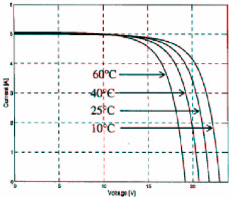
Figure 1.2: Voltage and Temperature Variations of a Photovoltaic Cell
The amount of power generated is proportional to the temperature, as Figure 3. demonstrates. The effect of temperature on the photovoltaic cells must be considered when calculating the maximum energy for a specific time of year. The curves in Figure 3. represent the point where the maximum power and voltage meet to deliver the highest output to the cell load.
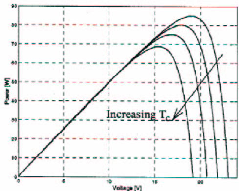
Figure 1.3: Output Power and the Effects of Temperature
How fast the system can recoup the installation cost depends on the yearly intensity of the sunlight. The energy that reaches the ground is called the solar insolation value. The southwest United States will recover the initial cost about two and a half times faster than systems in the Northeast, because the red area, in Figure 2.4, displays a high solar output region and the blue displays weak output locations. The number of sunny days compared with cloudy days determines the color variations, with the sunnier regions being in red. In winter, the farther a location is from the equator the less available energy there is due to shorter days.
CHAPTER-2
BASICS OF PHOTOVOLTAIC PANELS
2.1. SOLAR PANEL
A solar panel is made up of a semiconductor material that converts the light into energy through the use of a silicon composite p-n junction. When light hits any material, the energy is reflected, transmitted, or absorbed. The panel absorbs photons from the sunlight that produces excess electrons and holes in the material generating the current through the flow of electrons. For a photon to be absorbed, the energy it provides must exceed the semiconductor band gap energy. However, the closer the photon’s energy is to the band gap maximizes the cells efficiency and reduces the energy lost to heat. The addition of heat increases the internal resistance of the semiconductor and this increases the amount of energy needed for the electrons to escape the valence bond and thereby decreasing output power.
2.2. INTERNAL CHARACTERISTICS
The flow of electrons is equivalent to the amount of ambient light absorbed by the panel. The flow of electrons to the load stops when the light provided does not generate enough energy to allow the electrons to break free from their bonds. Equation (1) shows the output current of a cell and how it is affected by temperature, T, in Kelvin and the voltage of the cell, V. The component cell current is dependent on the photons, Il and the saturation current of the diode, Io. The constants are q= 1.6×10 joule and k= 1.38×10 j/K. Equation (2) represents the voltage of the cell as a function of the current drawn from the cell, I, and the photocurrent, I.
Figure 4. shows the basic design of a solar panel consisting of the semiconductor material as a fluctuating power source with a resistor that matches the internal resistance of the panel, a diode to direct the current flow, and a resistor for the resistance of the wires between the cells . The diode prevents a reverse bias current from flowing into the panel from the energy storage devices during the night. The internal resistances of the panel are represented by the shunt, Rsh, and the series resistance of the wires, R . The shunt value is very large and the series resistance is very small. These resistance values have little effect on the overall performance of the cells. The controller can be a MPPT or a DC converter, depending on the load. The silicon compound determines what light wavelengths will be absorbed by the panel and at what bandgap energy level . Energy levels below the bandgap pass through the panel as though it were transparent; those levels well above the bandgap are
reflected off the surface . 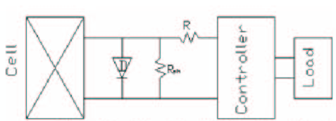
2.3. PHOTOVOLTAIC MATERIAL TYPES
The different elements, primarily silicon make up of the compound determine the efficiency of the panel; the main types are polycrystalline silicon, monocrystalline silicon, and amorphous silicon. Creating a p-n junction involves adding an impurity to the silicon wafer to provide holes and excess electrons to determine the size of the band gap for that compound. Phosphorous and boron are used as impurities in most silicon compounds. The higher the band gap, the more readily the compound will absorb photons. The efficiency of the panel is determined by how much of the sun’s light energy is absorbed by the semiconductor to generate current. The increased efficiency of the panel means more wattage can be produced from the same amount of light . Monocrystalline silicon is grown from a single silicon crystal into large crystalline blocks, which is sliced into a thin wafer that is doped to increase the photon absorption. This compound is expensive, but provides a high efficiency rate of 17%. Polycrystalline silicon is manufactured in the same way as the monocrystalline, but uses multiple crystals to grow the blocks to be cut into wafers. This process lowers the cost of production, and decreases the efficiency of the cells to 13%. Amorphous silicon is a thin film that is produced in long continuous strips that are many layers thick to maximize output. This is the cheapest and quickest process to produce solar panels, but has the lowest efficiency of all types of silicon compounds: 5% at most. The different chemical composition influences the way electrons flow, how much energy is needed to break the electrons from the valence bonds, and how temperature affects the current.
2.4. HARNESSING THE SUN’S ENERGY
A solar panel is made up of a collection of individual solar cells connected in series or parallel to maximize voltage or current output. The average voltage output for the individual cell is around half a Volt with a current of 400 milliamps. This is dependent on the efficiency of the silicon compound, temperature, and light conditions. A standard 12V panel is laid out with 36 individual cells that are wired into nine cells in series and the four rows in parallel to generate a maximum voltage of 17V to 30V at optimal conditions. The disadvantage of connecting the individual cell stems from varying differences between the cells. Shading and an underperforming cell causes localized power dissipation that is transformed into heat. The output power decrease is a combination of lost energy from the cell and the effects of reverse biasing of the cells that precede the affected one. If a cell completely fails, the row that it is located in will be shorted, considerably reducing the output to the panel. In Figure 5, the individual cells are shown in series with forward-biasing diodes to prevent current flow from an outside power source during the night. The more cells connected in series, the higher the voltage. To maximize the current, the cells will be connected in parallel. 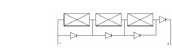
Figure 2.2: Photovoltaic Cells Connected in Series
2.5. SOLAR ELECTRICITY BASICS
Although solar electricity producing devices have been around for over 50 years, solar electricity devices, often referred to as photovoltaics or PV, are still considered cutting edge technology. The promise of clean, cheap, and abundant electricity from the sun has been the dream of many scientists and businesses. As a result each year a number of discoveries and advances for this technology have been made.
This primer has been designed to cover some of the basic concepts, components, and uses of PV. Explore each of the sections below to being your enlightening journey.
2.6. CURRENT PV TECHNOLOGY
Photovoltaic (PV) or solar cells as they are often called are semiconductor devices that convert sunlight into direct current (DC) electricity. Groups of PV cells are electrically configured into modules and arrays, which can be used to charge batteries, operate motors, and to power any number of electrical loads. With the appropriate power conversion equipment, PV systems can produce alternating current (AC) compatible with any conventional appliances, and can operate in parallel with, and interconnected to, the utility grid.
2.7. HISTORY OF PHOTOVOLTAICS
The first conventional photovoltaic cells were produced in the late 1950s, and throughout the 1960s were principally used to provide electrical power for earth-orbiting satellites. In the 1970s, improvements in manufacturing, performance and quality of PV modules helped to reduce costs and opened up a number of opportunities for powering remote terrestrial applications, including battery charging for navigational aids, signals, telecommunications equipment and other critical, low-power needs.
In the 1980s, photovoltaics became a popular power source for consumer electronic devices, including calculators, watches, radios, lanterns and other small battery-charging applications. Following the energy crises of the 1970s, significant efforts also began to develop PV power systems for residential and commercial uses, both for stand-alone, remote power as well as for utility-connected applications. During the same period, international applications for PV systems to power rural health clinics, refrigeration, water pumping, telecommunications, and off-grid households increased dramatically, and remain a major portion of the present world market for PV products. Today, the industry’s production of PV modules is growing at approximately 25 percent annually, and major programs in the U.S., Japan and Europe are rapidly accelerating the implementation of PV systems on buildings and interconnection to utility networks.
2.8. WORKING PRINCIPLE OF PV CELLS
Photovoltaic comes from word photo meaning “light” and volt a measurement of electricity. Some time photovoltaic cells are called PV cells or solar cells. The following four steps that show how a PV cell is made and how it produces electricity
From Silicon to Electricity 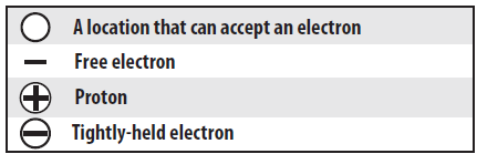
. Figure 2.3: Working Principle of PV (Symbol)
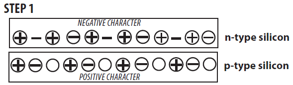
Figure 2.4: Working Principle of PV Step-1
A slab (or wafer) of pure silicon is used to make a PV cell. The top of the slab is very thinly diffused with an “n” dopant such as phosphorous. On the base of the slab a small amount of a “p” dopant, typically boron, is diffused. The boron side of the slab is 1,000 times thicker than the phosphorous side. Dopants are similar in atomic structure to the primary material. The phosphorous has one more electron in its outer shell than silicon, and the boron has one less. These dopants help create the electric field that motivates the energetic electrons out of the cell created when light strikes the PV cell.
- The phosphorous gives the wafer of silicon an excess of free electrons; it has a negative character. This is called the n-type silicon (n = negative). The n-type silicon is not charged—it has an equal number of protons and electrons—but some of the electrons are not held tightly to the atoms. They are free to move to different locations within the layer.
- The boron gives the base of the silicon a positive character, because it has a tendency to attract electrons. The base of the silicon is called p-type silicon (p = positive). The p-type silicon has an equal number of protons and electrons; it has a positive character but not a positive charge.
- Where the n-type silicon and p-type silicon meet, free electrons from the n-layer flow into the p-layer for a split second, then form a barrier to prevent more electrons from moving between the two sides. This point of contact and barrier is called the p-n junction.
- When both sides of the silicon slab are doped, there is a negative charge in the p-type section of the junction and a positive charge in the n-type section of the junction due to movement of the electrons and “holes” at the junction of the two types of materials. This imbalance in electrical charge at the p-n junction produces an electric field between the p-type and n-type silicon.
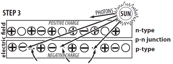 . Figure 2.6: Working Principle of PV Step-3
- If the PV cell is placed in the sun, photons of light strike the electrons in the p-n junction and energize them, knocking them free of their atoms. These electrons are attracted to the positive charge in the n-type silicon and repelled by the negative charge in the p-type silicon. Most photon-electron collisions actually occur in the silicon base.
- A conducting wire connects the p-type silicon to an electrical load, such as a light or battery, and then back to the n-type silicon, forming a complete circuit. As the free electrons are pushed into the n-type silicon they repel each other because they are of like charge. The wire provides a path for the electrons to move away from each other. This flow of electrons is an electric current that travels through the circuit from the n-type to the p-type silicon.
- In addition to the semi-conducting materials, solar cells consist of a top metallic grid or other electrical contact to collect electrons from the semi-conductor and transfer them to the external load, and a back contact layer to complete the electrical circuit.
2.9. CELLS AND ARRAYS
Photovoltaic cells are connected electrically in series and/or parallel circuits to produce higher voltages, currents and power levels. Photovoltaic modules consist of PV cell circuits sealed in an environmentally protective laminate, and are the fundamental building blocks of PV systems. Photovoltaic panels include one or more PV modules assembled as a pre-wired, field-installable unit. A photovoltaic array is the complete power-generating unit, consisting of any number of PV modules and panels.
The performance of PV modules and arrays are generally rated according to their maximum DC power output (watts) under Standard Test Conditions (STC). Standard Test Conditions are defined by a module (cell) operating temperature of 25o C (77o F), and incident solar irradiance level of 1000 W/m2 and under Air Mass 1.5 spectral distribution. Since these conditions are not always typical of how PV modules and arrays operate in the field, actual performance is usually 85 to 90 percent of the STC rating.
Today’s photovoltaic modules are extremely safe and reliable products, with minimal failure rates and projected service lifetimes of 20 to 30 years. Most major manufacturers offer warranties of 20 or more years for maintaining a high percentage of initial rated power output. When selecting PV modules, look for the product listing (UL), qualification testing and warranty information in the module manufacturer’s specifications.
2.10. PHOTOVOLTAIC SYSTEM COMPONENTS
Simply put, PV systems are like any other electrical power generating systems, just the equipment used is different than that used for conventional electromechanical generating systems. However, the principles of operation and interfacing with other electrical systems remain the same, and are guided by a well-established body of electrical codes and standards.
Although a PV array produces power when exposed to sunlight, a number of other components are required to properly conduct, control, convert, distribute, and store the energy produced by the array.
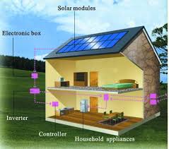
Depending on the functional and operational requirements of the system, the specific components required may include major components such as a DC-AC power inverter, battery bank, system and battery controller, auxiliary energy sources and sometimes the specified electrical load (appliances). In addition, an assortment of balance of system (BOS) hardware, including wiring, over current, surge protection and disconnect devices, and other power processing equipment. Figure 3 show a basic diagram of a photovoltaic system and the relationship of individual components.
2.11. BATTERIES USED IN PV SYSTEMS
Batteries are often used in PV systems for the purpose of storing energy produced by the PV array during the day, and to supply it to electrical loads as needed (during the night and periods of cloudy weather). Other reasons batteries are used in PV systems are to operate the PV array near its maximum power point, to power electrical loads at stable voltages, and to supply surge currents to electrical loads and inverters. In most cases, a battery charge controller is used in these systems to protect the battery from overcharge and over discharge.
2.12. TYPES OF PV SYSTEM
Photovoltaic power systems are generally classified according to their functional and operational requirements, their component configurations, and how the equipment is connected to other power sources and electrical loads. The two principal classifications are grid-connected or utility-interactive systems and stand-alone systems. Photovoltaic systems can be designed to provide DC and/or AC power service, can operate interconnected with or independent of the utility grid, and can be connected with other energy sources and energy storage systems.
Grid-connected or utility-interactive PV systems are designed to operate in parallel with and interconnected with the electric utility grid. The primary component in grid-connected PV systems is the inverter, or power conditioning unit (PCU). The PCU converts the DC power produced by the PV array into AC power consistent with the voltage and power quality requirements of the utility grid, and automatically stops supplying power to the grid when the utility grid is not energized. A bi-directional interface is made between the PV system AC output circuits and the electric utility network, typically at an on-site distribution panel or service entrance. This allows the AC power produced by the PV system to either supply on-site electrical loads, or to back-feed the grid when the PV system output is greater than the on-site load demand. At night and during other periods when the electrical loads are greater than the PV system output, the balance of power required by the loads is received from the electric utility This safety feature is required in all grid-connected PV systems, and ensures that the PV system will not continue to operate and feed back into the utility grid when the grid is down for service or repair.
Figure 2.11: Diagram of grid-connected photovoltaic system.
2.13. STAND-ALONE PHOTOVOLTAIC SYSTEMS
Stand-alone PV systems are designed to operate independent of the electric utility grid, and are generally designed and sized to supply certain DC and/or AC electrical loads. These types of systems may be powered by a PV array only, or may use wind, an engine-generator or utility power as an auxiliary power source in what is called a PV-hybrid system. The simplest type of stand-alone PV system is a direct-coupled system, where the DC output of a PV module or array is directly connected to a DC load (Figure 5). Since there is no electrical energy storage (batteries) in direct-coupled systems, the load only operates during sunlight hours, making these designs suitable for common applications such as ventilation fans, water pumps, and small circulation pumps for solar thermal water heating systems. Matching the impedance of the electrical load to the maximum power output of the PV array is a critical part of designing well-performing direct-coupled system. For certain loads such as positive-displacement water pumps, a type of electronic DC-DC converter, called a maximum power point tracker (MPPT), is used between the array and load to help better utilize the available array maximum power output.
In many stand-alone PV systems, batteries are used for energy storage. Figure 6 shows a diagram of a typical stand-alone PV system powering DC and AC loads. Figure 7 shows how a typical PV hybrid system might be configured.
2.14. HOW PV CELLS ARE MADE
The process of fabricating conventional single- and polycrystalline silicon PV cells begins with very pure semiconductor-grade polysilicon – a material processed from quartz and used extensively throughout the electronics industry. The polysilicon is then heated to melting temperature, and trace amounts of boron are added to the melt to create a P-type semiconductor material. Next, an ingot, or block of silicon is formed, commonly using one of two methods: 1) by growing a pure crystalline silicon ingot from a seed crystal drawn from the molten polysilicon or 2) by casting the molten polysilicon in a block, creating a polycrystalline silicon material. Individual wafers are then sliced from the ingots using wire saws and then subjected to a surface etching process. After the wafers are cleaned, they are placed in a phosphorus diffusion furnace, creating a thin N-type semiconductor layer around the entire outer surface of the cell. Next, an anti-reflective coating is applied to the top surface of the cell, and electrical contacts are imprinted on the top (negative) surface of the cell. An aluminized conductive material is deposited on the back (positive) surface of each cell, restoring the P-type properties of the back surface by displacing the diffused phosphorus layer. Each cell is then electrically tested, sorted based on current output, and electrically connected to other cells to form cell circuits for assembly in PV modules.
2.15. THIN FILM PHOTOVOLTAICS
Thin-film photovoltaic modules are manufactured by depositing ultra-thin layers of semiconductor material on a glass or thin stainless-steel substrate in a vacuum chamber. A laser-scribing process is used to separate and weld the electrical connections between individual cells in a module. Thin-film photovoltaic materials offer great promise for reducing the materials requirements and manufacturing costs of PV modules and systems.
2.16. PROS AND CONS OF PV
Photovoltaic systems have a number of merits and unique advantages over conventional power-generating technologies. PV systems can be designed for a variety of applications and operational requirements, and can be used for either centralized or distributed power generation. PV systems have no moving parts, are modular, easily expandable and even transportable in some cases. Energy independence and environmental compatibility are two attractive features of PV systems. The fuel (sunlight) is free, and no noise or pollution is created from operating PV systems. In general, PV systems that are well designed and properly installed require minimal maintenance and have long service lifetimes.
At present, the high cost of PV modules and equipment (as compared to conventional energy sources) is the primary limiting factor for the technology. Consequently, the economic value of PV systems is realized over many years. In some cases, the surface area requirements for PV arrays may be a limiting factor. Due to the diffuse nature of sunlight and the existing sunlight to electrical energy conversion efficiencies of photovoltaic devices, surface area requirements for PV array installations are on the order of 8 to 12 m^2 (86 to 129 ft^2) per kilowatt of installed peak array capacity.CHAPTER- 3
- PHOTOVOLTAIC (PV) SYSTEM DESIGN AND INSTALLATION
3.1. INTRODUCTION
Photovoltaic (PV) power systems convert sunlight directly into electricity. A residential PV power system enables a homeowner to generate some or all of their daily electrical energy demand on their own roof, exchanging daytime excess power for future energy needs (i.e. nighttime usage). The house remains connected to the electric utility at all times, so any power needed above what the solar system can produce is simply drawn from the utility. PV systems can also include battery backup or uninterruptible power supply (UPS) capability to operate selected circuits in the residence for hours or days during a utility outage. The purpose of this document is to provide tools and guidelines for the installer to help ensure that residential photovoltaic power systems are properly specified and installed, resulting in a system that operates to its design potential. This document sets out key criteria that describe a quality system, and key design and installation considerations that should be met to achieve this goal. This document deals with systems located on residences that are connected to utility power, and does not address the special issues of homes that are remote from utility power.
In this early stage of marketing solar electric power systems to the residential market, it is advisable for an installer to work with well established firms that have complete, pre-engineered packaged solutions that accommodate variations in models, rather than custom designing custom systems. Once a system design has been chosen, attention to installation detail is critically important. Recent studies have found that 10-20% of new PV installations have serious installation problems that will result in significantly decreased performance. In many of these cases, the performance shortfalls could have been eliminated with proper attention to the details of the installation.
3.2. BASIC PRINCIPLES OF A QUALITY PV SYSTEM
1. Select a packaged system that meets the owner’s needs. Customer criteria for a system may include reduction in monthly electricity bill, environmental benefits, desire for backup power, initial budget constraints, etc. Size and orient the PV array to provide the expected electrical power and energy.
2. Ensure the roof area or other installation site is capable of handling the desired system size.
3. Specify sunlight and weather resistant materials for all outdoor equipment.
4. Locate the array to minimize shading from foliage, vent pipes, and adjacent structures.
5. Design the system in compliance with all applicable building and electrical codes.
6. Design the system with a minimum of electrical losses due to wiring, fuses, switches, and inverters.
7. Properly house and manage the battery system, should batteries be required.
8. Ensure the design meets local utility interconnection requirements.
3.3. BASIC STEPS TO FOLLOW WHEN INSTALLING A PV SYSTEM
1. Ensure the roof area or other installation site is capable of handling the desired system size.
2. If roof mounted, verify that the roof is capable of handling additional weight of PV system. Augment roof
structure as necessary.
3. Properly seal any roof penetrations with roofing industry approved sealing methods.
4. Install equipment according to manufacturers specifications, using installation requirements and
procedures from the manufacturers’ specifications.
5. Properly ground the system parts to reduce the threat of shock hazards and induced surges.
6. Check for proper PV system operation by following the checkout procedures on the PV System Installation Checklist.
7. Ensure the design meets local utility interconnection requirements
8. Have final inspections completed by the Authority Having Jurisdiction (AHJ) and the utility (if required).
3.4. SYSTEM DESIGN CONSIDERATIONS
3.4.1. PV ELECTRICAL SYSTEM TYPES
There are two general types of electrical designs for PV power systems for homes; systems that interact with the utility power grid and have no battery backup capability; and systems that interact and include battery backup as well.
3.4.2. GRID-INTERACTIVE ONLY (NO BATTERY BACKUP)
This type of system only operates when the utility is available. Since utility outages are rare, this system will normally provide the greatest amount of bill savings to the customer per dollar of investment. However, in the event of an outage, the system is designed to shut down until utility power is restored. Typical System Components:
PV Array: A PV Array is made up of PV modules, which are environmentally-sealed collections of PV Cells—
the devices that convert sunlight to electricity. The most common PV module that is 5-to-25 square feet in size and weighs about 3-4 lbs./ft2. Often sets of four or more smaller modules are framed or attached together by struts in what is called a panel. This panel is typically around 20-35 square feet in area for ease of handling on a roof. This allows some assembly and wiring functions to be done on the ground if called for by the installation instructions. Balance of system equipment (BOS): BOS includes mounting systems and wiring systems used to integrate the solar modules into the structural and electrical systems of the home. The wiring systems include disconnects for the dc and ac sides of the inverter, ground-fault protection, and over current protection for the solar modules. Most systems include a combiner board of some kind since most modules require fusing for each module source circuit. Some inverters include this fusing and combining function within the inverter enclosure.
dc-ac inverter: This is the device that takes the dc power from the PV array and converts it into standard ac power used by the house appliances. metering: This includes meters to provide indication of system performance. Some meters can indicate home energy usage. Other components: utility switch (depending on local utility)
3.4.3. GRID-INTERACTIVE WITH BATTERY BACKUP
This type of system incorporates energy storage in the form of a battery to keep “critical load” circuits in the house operating during a utility outage. When an outage occurs the unit disconnects from the
Utility and powers specific circuits in the home. These critical load circuits are wired from a sub panel that is separate from the rest of the electrical circuits. If the outage occurs during daylight hours, the PV array is able to assist the battery in supplying the house loads. If the outage occurs at night, the battery supplies the load. The amount of time critical loads can operate depends on the amount of power they consume and the energy stored in the battery system. A typical backup battery system may provide about 8kWh of energy storage at an 8-hour discharge rate, which means that the battery will operate a 1-kW load for 8 hours. A 1-kW load is the average usage for a home when not running an air conditioner.
Typical System Components:
In addition to components listed in 2.1.1., a battery backup system may include some or all of the following:
1. Batteries and battery enclosures
2. Battery charge controller
3. Separate sub panel(s) for critical load circuits
3.5. MOUNTING OPTIONS
There are several ways to install a PV array at a residence. Most PV systems produce 5-to-10 Watts per square foot of array area. This is based on a variety of different technologies and the varying efficiency of different PV products. A typical 2- kW PV system will need 200-400 square feet of unobstructed area to site the system. Consideration should also be given for access to the system. This access space can add up to 20% of needed area to the mounting area required.
3.5.1 ROOF MOUNT
Often the most convenient and appropriate place to put the PV array is on the roof of the building. The PV array may be mounted above and parallel to the roof surface with a standoff of several inches for cooling purposes. Sometimes, such as with flat roofs,
a separate structure with a more optimal tilt angle is mounted on the roof. Proper roof mounting can be labor intensive. Particular attention must be paid to the roof structure and the weather sealing of roof penetrations. It is typical to have one support bracket
for every 100 Watts of PV modules. For new construction, support brackets are usually mounted after the roof decking is applied and before the roofing materials is installed. The crew in charge of laying out the array mounting system normally installs the brackets. The roofing contractor can then flash around the brackets as they install the roof. A simple installation detail and a sample of the support bracket is often all that is needed for a roofing contractor to estimate the flashing cost. Masonry roofs are often structurally designed near the limit of their weight-bearing capacity. In this case, the roof structure must either be enhanced to handle the additional weight of the PV system or the masonry roof transitioned to composition shingles in the area where the PV array
is to be mounted. By transitioning to a lighter roofing product, there is no need to reinforce the roof structure since the combined weight of composite shingles and PV array is usually less than the displaced masonry product.
3.5.2 SHADE STRUCTURE
An alternative to roof mounting is to mount the system as a shade structure. A shade structure may be a patio cover or deck shade trellis where the PV array becomes the shade. These shade systems can support small to large PV systems. The construction cost with a PV system is a little different than for a standard patio cover, especially if the PV array is acts as part or the entire shade roof. If the PV array is mounted at a steeper angle than a typical shade structure, additional structural enhancements may be necessary to handle the additional wind loads. The weight of the PV array is 3-to-5 lbs./ft2, which is well within structural limits of most shade support structures. The avoided cost of installing roof
brackets and the associated labor could be counted toward the cost of a fully constructed patio cover. The overall cost of this option will likely be higher than roof mounting, but the value of the shade often offsets the additional costs. Other issues to consider include simplified array access for maintenance
Module wiring, if visible from underneath, must be carefully Concealed to keep the installation aesthetically pleasing
Cannot grow vines, or must be diligent about keeping it trimmed back from modules and wiring
3.6. ESTIMATING SYSTEM OUTPUT
PV systems produce power in proportion to the intensity of sunlight striking the solar array surface. The intensity of light on a surface varies throughout a day, as well as day to day, so the actual output of a solar power system can vary substantial. There are other factors that affect the output of a solar power system. These factors need to be understood so that the customer has realistic expectations of overall system output and economic benefits under variable weather conditions over time.
3.6.1. FACTORS AFFECTING OUTPUT STANDARD TEST CONDITIONS
Solar modules produce dc electricity. The dc output of solar modules is rated by manufacturers under Standard Test Conditions (STC). These conditions are easily recreated in a factory, and allow for consistent comparisons of products, but need to be modified to estimate output under common outdoor operating conditions. STC conditions are: solar cell temperature = 25°C; solar irradiance (intensity) = 1000 W/m2
(often referred to as peak sunlight intensity, comparable to clear summer noon time intensity); and solar spectrum as filtered by passing through 1.5 thickness of atmosphere (ASTM Standard Spectrum). A manufacturer may rate a particular solar module output at 100 Watts of power under STC, and call the product a “100-watt solar module.” This module will often have a production tolerance of +/-5% of the rating,
Which means that the module can produce 95 Watts and still be called a “100-watt module.” To be conservative, it is best to use the low end of the power output spectrum as a starting point (95 Watts for a 100-watt module). Temperature Module output power reduces as module temperature increases. When operating on a roof, a solar module
will heat up substantially, reaching inner temperatures of 50-75°C. For crystalline modules, a typical temperature reduction factor recommended by the CEC is 89% or 0.89. So the “100-watt” module will typically operate at about 85 Watts (95 Watts x 0.89 = 85 Watts) in the middle of a spring or fall day, under full sunlight conditions.
Dirt and dust Dirt and dust can accumulate on the solar module surface, blocking some of the sunlight and reducing output. Much of California has a rainy season and a dry season. Although typical dirt and dust is cleaned off during every rainy season, it is more realistic to estimate system output taking into account the reduction due to dust buildup in the dry season. A typical annual dust reduction factor to use is 93% or 0.93. So the “100- watt module,” operating with some accumulated dust may operate on average at about 79 Watts (85 Watts x 0.93 = 79 Watts). Mismatch and wiring losses
The maximum power output of the total PV array is always less than the sum of the maximum output of the individual modules. This difference is a result of slight inconsistencies in performance from one module to the next and is called module mismatch and amounts to at least a 2% loss in system power. Power is also lost to resistance in the system wiring. These losses should be kept to a minimum but it is difficult to keep these losses below 3% for the system. A reasonable reduction factor for these losses is 95% or 0.95. Dc to ac conversion losses the dc power generated by the solar module must be converted into common household ac power using an inverter. Some power is lost in the conversion process, and there are additional losses in the wires from the rooftop array down to the inverter and out to the house panel. Modern inverters commonly used in residential PV power systems have peak efficiencies of 92-94% indicated by their manufacturers, but these again are measured under well- controlled factory conditions. Actual field conditions usually result in overall dc-to-ac
conversion efficiencies of about 88-92%, with 90% or 0.90 a reasonable compromise.
So the “100-watt module” output, reduced by production tolerance, heat, dust, wiring, ac conversion, and other losses will translate into about 68 Watts of AC power delivered to the house panel during the middle of a clear day (100 Watts x 0.95 x 0.89 x 0.93 x 0.95 x 0.90 = 67 Watts).
CHAPTER-4
SOLAR PHOTOVOLTAICS SYSTEM
4.1. FORMS OF PHOTOVOLTAIC ENERGY
Photovoltaic energy comes in three forms: stand-alone, grid-connected, and hybrid system. Stand-alone systems employ a completely independent operation that stores energy in batteries for nighttime usage. The grid-connected form connects directly to the power grid, eliminating the need for batteries. Tying into the grid increases the number of individual users that utilize solar energy on a small scale, and provides the dependability of continuous power no matter the cloud conditions. A hybrid system combines the consistency of the grid with a battery backup, in case grid power is lost.
4.2. GRID VS. OFF-GRID SYSTEM
Isolated areas and mobile systems are dependent on batteries, whereas places in town have the option of using a power grid, depending on their power consumption and power suppliers. Connecting to a power grid allows the power generated from the panels to be back-fed to the grid when the sun is out, and to run the structure off the line when the sun is down. The cost of purchasing a DC to AC converter with a grid controller, compared to using batteries, varies by the size of the system. Reliance on a grid eliminates the need to replace faulty batteries that plague the long-term operation of stand-alone systems. The drawback to grid-connected systems is the number of panels that are needed to provide enough power for the utility company to consider connecting the system to the grid. A grid-connected system must meet the following criteria to function: voltage regulation, frequency regulation, power factor control, harmonic distortion controls, and quick response time. The amount of power a system generates determines if the energy provided will decrease the amount of the electric bill, or if the excess energy produced would be sold to the power company. During the summer months, high temperatures place increased demand on the power grid due to the large amount of electricity used by air conditioners. Periods of extreme heat are the result of favorable conditions for the sun’s energy to reach the Earth’s surface. The use of solar panels can supplement the power requirements of the air conditioning system during the period of the day when the temperature reaches its maximum level. Figure 6, represents the system required to connect the panel to the power grid. A DC-to-DC converter is needed to hold a near constant output voltage. To maximize the output of the panel, a maximum power point tracker (MPPT) controller is used. A MPPT is a boost converter for a single panel or a buck converter when multiple panels are combined in series. The converters produce a near constant voltage value that increases the efficiency of the inverter. The capacitor removes any small variations in the near-constant input voltage to the DC-AC converter. The inverter monitors the power grid to match the standard voltage and frequency. The controller continuously compares the frequency of the grid with the inverter, and adjusts the duty ratio to counter frequency variations.
4.3. HYBRID SYSTEMS
A system design that combines the advantages of both a stand-alone setup and a grid-connected setup is deemed a hybrid system. This system relies on the coordination of multiple controllers to continuously monitor the flow of power from the solar panels, and regulate the power to fulfill the needs of the structure, replenish the reserve batteries, and manage the flow of energy to and from the power grid. The basic setup of a hybrid system is shown in Figure 7. The equipment consists of the solar panels, a MPPT, a charge controller, batteries, and an inverter. The charge controller monitors the batteries and determines whether or not to charge them. The high-end inverter matches the frequency of the power grid and monitors the grid to detect any loss in power. This system provides an uninterruptible power supply that provides electricity even when the power grid is offline. This system has the highest cost and requires the replacement and maintained of batteries. The use of this type is limited to industrial applications where backup power may be needed to prevent the stoppage of equipment due to a trip in the power grid.
4.4. STAND-ALONE SYSTEMS
The earliest application of solar energy was on satellites orbiting the Earth. The first satellites operated for on internal energy sources that lasted for a week to a few months. The first application of a stand-alone system came incorporating solar panels to the satellite to lengthen the operational lifespan to years. The lessons learned from the space program are being incorporated in areas of the world that are secluded from modern civilizations. These locations are removed from conventional power supplies and rely on electricity produced by gasoline generators. The growing expense of fuel has increased the demand from third-world countries governments to invest in solar energy. In isolated regions that require constant electricity, the primary source of power is solar, with gasoline generators for backup. This stand-alone hybrid provides the reserve power during periods of poor solar insulation, where other designs rely on large battery banks. These hybrid systems are dependent on the cost to transport the fuel and with increasing fuel costs are promoting the conversion to straight solar with the generators as emergency backup. Stand-alone systems can be built to power small loads, like water pumps and streetlights, to the vast loads of a house. The equipment required to build a stand-alone system includes a solar panel, a voltage controller, and batteries. For loads that require AC power, an inverter would be added to the design. To control the output voltage of a panel, an MPPT is employed to increase the efficiency of the power to the batteries and load. The components of each system vary due to the size of the load and the hours of operation during the night. For projects that operate during the day, the battery may only need to last minutes to hours, depending on the load. Systems that have loads that operate at night require determining the number of hours the load operates and from this the panel and batteries are selected. Dependability of the load must be considered to determine the amount of reserve energy the system must have to provide continuous operation. The advantages of a stand-alone system are independent from the power grid, replacement of petroleum-fueled generators, and cost effective compared to running the power lines to remote areas. The disadvantages are the availability of the grid power to most locations, the cost and replacement of equipment, and the loss of power during periods of poor solar insulation.
CHAPTER-5
PV CHARGE CONTROLLER
SBC-7108 / 7112 / 7120
5.1. Precautions Specifications
1. Before using the charge/load controller, read all the instructions and cautionary markings on the charge/load controller, the batteries and the photovoltaic panels.
2. Do not attempt to repair the controller. Incorrect re-assembly may result in a risk of electric shock or fire.
3. To reduce risk of electric shock, disconnect all wiring before attempting any maintenance or cleaning. Turning off controls will not reduce this risk. PV panels produce power when exposed to light – cover them with opaque material before servicing.
4. Working in Vicinity of a Lead Acid Battery is dangerous. Batteries generate EXPLOSIVE gases during normal operation. Provide ventilation to outdoors from the highest point of the battery compartment.
5. This charge/load controller is intended to be used with a battery supply of 12 VDC nominal voltage.
6. Be extra cautious to reduce the possibility of dropping a metal tool onto batteries. It might spark or short-circuit batteries or other electrical parts that may cause explosion. Cover wrench handles with plastic tape or vinyl dip coating material.
SBC-7100 Series
Models
7108
7112
7120
Battery voltage 12V
Maximum PV panel open circuit voltage 26V
Continuous load/charge current 8A
12A
20A
Maximum charge current (5 mins) 10A
15A
25A
Maximum load current (5 mins) 10A
20A
25A
Operation current(no Load and no PV) 30mA
Voltage across terminals (PV to Battery) 0.6V
0.6V
0.8V
Voltage across terminals (Battery to Load) 0.3V
0.3V
0.4V
Electronic Blocking
- If the PV cell is placed in the sun, photons of light strike the electrons in the p-n junction and energize them, knocking them free of their atoms. These electrons are attracted to the positive charge in the n-type silicon and repelled by the negative charge in the p-type silicon. Most photon-electron collisions actually occur in the silicon base.
- The boron gives the base of the silicon a positive character, because it has a tendency to attract electrons. The base of the silicon is called p-type silicon (p = positive). The p-type silicon has an equal number of protons and electrons; it has a positive character but not a positive charge.
(To protect against reverse polarity connection of PV panel and to block current from battery to PV panel when voltage of battery is higher than PV panel)
Yes
Battery reverse polarity protection
Yes
Overcharge & Over-discharge protection
Yes
Battery status LED indication
5-State LED Indications
Charging status indication
3-State LCD Display
Recommended wire size
#12AWG
Weight
0.47kg
Dimension (W x D x H)
150x 85x 45 mm
Fuse
15A
20A
30A
Operating ambient temperature
-10 to 50 °C
Over temperature protection
Yes
Battery charging float voltage setting
Adjustable from 12.0-15.0V
Battery charging bulk voltage setting DC load control mode (For DC load terminal):
Adjustable from 12.0-16.0V
Low Voltage Disconnect(LVD)
Adjustable from 8-16V
Low Voltage Reconnect(LVR)
Adjustable from 8-16V
5.2. Introduction
The SBC-7108/7112/7120 PV Charge Controller is designed for use with all types of 12V photovoltaic (PV) panels/systems and different types of 12V batteries, such as wet or sealed lead acid, lead calcium, lead antimony battery.
Numerous features are provided to maximize the performance of the system:
-Electronic Blocking ( To protect against reverse polarity connection of PV panel and block current from battery to PV Panel when voltage of Battery is higher than PV panel),
– Suitable for PV panels with Open Circuit Voltage from 17 to 23V,
– Rated charging/load current 8A (SBC-7108)/ 12A(SBC-7112) / 20A(SBC-7120),
– PWM Charging with 3-stage Charge Control (to allow battery be left unattended for long period),
– User Adjustable Charge Control Settings for different types of batteries,
– User Adjustable Low Voltage Disconnect and Low Voltage Reconnect,
– Build-In Microprocessor for PV charge control to maximize the charging efficiency,
– Overcharge and Over-discharge Protection,
– Over Temperature Protection,
– Short-Circuit Protection at load terminal (4) & Battery Reverse Polarity Protection at Battery Connection Terminal (5),
– Informative LCD Display and Tri-Color LED indication of system and battery conditions,
– Optional Temperature Sensor for compensated battery charging,
– Optional Remote Signal Terminal.
5.3. CONTROL AND INDICATOR
The following diagram shows the hardware interface of the PV Charge Controller.
1. Battery LED Indicator
2. LCD Display
3. Reset button (see Section 3.4)
4. Temperature Sensor (Optional )
5. 12V DC Load terminal with Low Voltage Disconnect/NIGHT-LIGHT mode
6. 12V Battery connection terminal
7. PV Panel connection terminal
5.4.. INSTALLATION AND INDICATION
5.4.1. CONNECTION
The PV Charge Controller should be connected as follow:
This controller has Electronic Blocking feature, therefore, it is not necessary to connect a diode between the PV module and the Controller.
The recommended wire size is #12AWG (SBC-7108/7112) / #10AWG (SBC7120).
It is recommended that the PV Charge Controller should be installed in a dry, sheltered location away from sources of high temperature and moisture.
5.4.2. LED INDICATOR
| Red Flashing…… | Battery Voltage is lower than 12.6V |
| Constant Red… | Battery Voltage has reached Low Voltage Disconnect(LVD) |
| Constant Green | Battery Voltage is higher than 12.6V |
| Green Flashing | Battery Voltage has reached Bulk Charging Setting (Fully Charged) |
| Orange Flashing | Battery Voltage is lower than Low Voltage Disconnect (LVD) |
Voltage Setting and load has been disconnected.Red-Green FlashingEqualization Charging in process.
Table 5.2: LED Indications
5.4.3. LCD DISPLAY
The LCD Display shows the battery voltage, PV panel voltage and the charging modes during normal day time operation. At night time or low sunlight or PV disconnected situation, display of PV VOLT value is to be ignored .
LCD DISPLAY Descriptions
BATT VOLT……..Shows the Battery Voltage
PV VOLT…………Shows the PV panel Input Voltage to the system
PV CURR………..Shows the PV panel Input Current to the system
TOD PV_AH…….Shows the total Ampere-Hour input to the system in current day
L1D PV_AH……..Shows the total Ampere-Hour input to the system a day before
L2D PV_AH……..Shows the total Ampere-Hour input to the system 2 days before
CHARGING STATUS
BULK CHARGE……….. Shows the charging process is in Bulk charge
ABSORB CHARGE…… Shows the charging process is in Absorption charge
FLOAT CHARGE……… Shows the charging process is in Float charge
EQULIZ CHARGE…….. Shows the charging process is in Equalization charge
PV < BATT VOLT…….. Indicates the PV voltage is less than the Battery Voltage
5.5. ADJUST THE PV CHARGE CONTROLLER SETTINGS
Factory Preset
The following table shows the factory preset values of the PV Charge Controller:
Bulk Voltage………………………………………….. 14.3V
Float Voltage………………………………………….. 13.5V
Low Voltage Disconnect………………………….. 11.5V
Low Voltage Reconnect…………………………… 12.5V
Night Light Mode Option…………………………. Off
Table 5.3: Preset values of the adjustable parameters
The preset Bulk and Float Set points are for typical Sealed Gel-type Lead Acid Battery only. For typical wet-type Lead Acid Battery, set Bulk set point to 14.8V and Float set point to 13.5V.
Please refer to battery manufacturer’s specific recommended values.
Adjust the charging voltage, battery protection and night-light mode duration settings
1. Make sure all the dip switches are switched to OFF position. (Section 3.4.2 table 4)
2. Disconnect the negative terminal of the battery from the PV Controller.
3. Press the Reset button and keep the Reset button being pressed. At the same time, connect the negative terminal of the battery back to the Controller.
4. When the LED is flashing green, release the Reset button as Setting Mode has been entered.
5. Each subsequent press of the Reset button will move on to the next setting in the cycle as shown in Fig. 4:
6. You can press the Set-button 1 and 2 to adjust the desired setting.
7. When all the desired settings are done, switch the dip switch 2 to ON position to store the new settings and resume to normal operation. Then, switch the dip switch 2 to OFF.
5.6. PV CHARGE CONTROL MODE
The SBC-7112 PV Charge Controller can operate in the several modes. This includes the 3-stage Charge Control, Equalization Charging Mode, DC Load Control Mode, NIGHT-LIGHT mode, Temperature Sensing and Over Temperature Protection features.
5.7. 3-STAGE CHARGE CONTROL
The main function of charge controller is to regulate the flow of electricity from the photovoltaic panels to the batteries. In PV systems with batteries, the batteries must be protected from overcharging and be maintained at fully charged state.
The PV Charge Controller uses the Micro-Processor and PWM ( Pulse Width Modulation ) to give optimal and safe charging .
It makes varying On-Off pulses of electrical energy from the photovoltaic(PV) panel in charging the battery according to the battery state. It has 3 stages of charging, as follows:
a. BULK CHARGE – At this mode, a preset maximum constant amount of current (amps) is fed into the battery as the no PWM is present. As the battery is being charged up , the voltage of the battery increases gradually.
b. ABSORPTION CHARGE – After the preset voltage is reached (approximately 14.3 volts for a 12 volt system) the voltage is then held constant. As the battery continues to be charged at constant voltage, the charging current decreases. The charging voltage is held at the Bulk Voltage Setting for one full hour with various rapid On-Off pulses (PWM). It then switches to Float Charge Mode.
c. FLOAT CHARGE –The controller will maintain the battery voltage at the float voltage setting by giving shorter On-pulse charge to make up for any detected self discharge of the battery. When the battery voltage drops below the Float Voltage Setting for a total period of 10 minutes, a new charging cycle is activated in Bulk or Absorption Charge.
The three stages charging method works well with the chemical reaction that occurs as a battery is being charged. When a battery is more discharged, a regulated maximum current can be applied, since there is a lot of material available for the reactions to occur.
As the battery refills, less and less chemical material is available for the reaction. By using PWM to slowly reducing the charge current, while maintaining a preset high voltage, the battery is more closely refilled at the reaction rate of the chemicals. Finally, the Float voltage keeps the battery fully charged at all times taking care of the self discharge .
Remarks:
1. When the Battery is charged up to Bulk Charge Voltage setting, the LCD will only show the
Bulk charge voltage one or two times quickly, then the PV controller switches to Absorption charge
2. The “Batt Volt” display during Absorption charge is less than Bulk Voltage Setting. The difference will decrease as the Absorption time increase.
3. The “Batt Volt” display during Float Charge is less than the Float Charge Voltage Setting.
5.8. EQUALIZATION CHARGING MODE (AUTOMATIC OR MANUAL)
WARNING: Equalization Charging is only for Wet-type Lead Acid Battery.
The Equalization Charging Voltage is factory pre-set to the Bulk Voltage + 1 Volt.
The battery manufacturer should be consulted. Clean, distilled water will need to be added to the battery AFTER the equalization process.
5.8.1. AUTOMATIC EQUALIZATION CHARGING
Automatic Equalization charge is only available when battery voltage is higher than the Low Voltage Disconnect (LVD) voltage , see 4.3.1.
To set Automatic Equalization Charging, set the dip switch 2 to OFF position.
The PV Charge Controller will perform Equalization charging for 2 hours once every 30 days During equalization charge , it can be stopped any time by pressing the Reset button once and the controller will return to the charging mode before the Equalization charge.
5.8.2. MANUAL EQUALIZATION CHARGING
Set the Night-Light Mode , dip switch 3 to off position. Press and hold the Reset button for 10seconds and the equalization charge will go on for two hour.
During equalization charge , it can be stopped any time by pressing the Reset button once and the controller will return to the charging mode before the Equalization charge.
5.9. 12V DC LOAD TERMINAL – CONTROL MODE
The 12V DC load terminal is designed for low power DC load such as street light.
It prevents over-discharging the battery and has 10 Night-Light timer programs.
5.9.1. LOW VOLTAGE DISCONNECT (LVD)
When the battery voltage is lower than the Low Voltage Disconnect (LVD) setting, the LED will blink orange once every 2 seconds. After it has flashed several times (up to 5), the load will be cut off. After the load is cut off, user can press the Reset button once to switch on the load for a grace period of 10 minutes for emergency purpose.
5.9.2. LOW VOLTAGE RECONNECT (LVR)
When the battery voltage is higher than Low Voltage Reconnect (LVR) setting, the controller will automatically reconnect the load.
5.10. NIGHT-LIGHT MODE PROGRAMS
In the night-light mode, we have 10 selections.
To Activate the NIGHT-LIGHT Mode, switch the dipswitch 3 to ON position.
After activating, when the PV panel voltage is lower than 3.5V for 10 minute, the Controller will turn on the light for a preset period of time according to the option selected. When the PV panel voltage is higher than 3.5V for 10minute, the Controller will turn off the light. In NIGHT-LIGHT Mode, press and hold the Reset button can switch on the Light to test the light.
Also, when the battery is lower than the Low Voltage Disconnect (LVD) for 2 minutes, the load will be cut off. When the battery voltage becomes higher than Low Voltage Reconnect (LVR) setting, the controller will automatically reconnect the load again.
5.11. MEASURE NIGHT LENGTH
The load timer options that turn the load on again before sunrise require that the PV charge controller to measure the length of the night. The default value of night length is 12 hours after installation (or disconnect then reconnect the battery). The local length of night will take the moving average of 4 consecutive nights.
If the solar array is disconnected during service, the controller will then record premature night duration. This wrong night length data will be outdated after another 4 days of normal service.
Alternatively, the above error can be corrected by disconnect then reconnect the battery.
5.12. TEMPERATURE SENSOR (OPTIONAL)
When an external temperature sensor (optional accessory) is installed, the controller will adjust the Bulk and Float Charge Voltage according to the temperature of the battery type. The regulation set point is 25ºC. The Controller adjusts the BULK and FLOAT set points -0.03V/ ºC. Only the factory provided temperature sensor (optional accessory) can be used. If no temperature sensor is installed, the controller will set the temperature of the battery at 25ºC.
5.13. OVER TEMPERATURE PROTECTION
The operation temperature of the transistors of the PV Charge Controller is also continuously monitored. If excessive temperature is detected, the charge controller transistors will repeatedly and rapidly turn On and Off to reduce the charging rate so as to reduce the transistors’ temperature. In case the charging current (from the solar panel) is reduced to zero and over temperature condition still persists, the load will also be disconnected. When the temperature has dropped to the working range, the PV panel and the load will be connected again.
CHAPTER-6
GLOBAL SOLAR ENERGY SECTOR
6.1. INTRODUCTION.
There is a looming energy crisis world-wide. It arises not only from shrinking reserves of fossil fuels and the public concern on the continued use of fossil fuel for energy generation, but also from ageing nuclear power plants (in the developed countries) which are going to cease operation in a relatively near future. There is a global realization that fossil fuel usage must be reduced drastically in order to arrest green house gas (mainly CO2) emission to the atmosphere, which causes global warming. In fact, this aspect of global warming, rather than the imminent shortage of fossil fuel, that is propelling all industrialized countries, in the West as well as in the East, into taking urgent actions now. Commercial nuclear power all over the world is undergoing an unprecedented revival. But some countries, such as Germany, Italy and few others, are reluctant to jump into the nuclear bandwagon and, instead, concentrating on research and development of alternative sources of energy, particularly the solar energy.
Even when countries are expanding nuclear capabilities, they are also undertaking development of alternative energies such as solar power, wind power, geothermal power etc. as part of energy mix. Out of these alternative sources, solar power seems very promising.
6.2 WORLD WIDE GROWTH OF SOLAR PHOTOVOLTAIC POWER
The following diagram, Figure 1, shows the world wide growth of solar photovoltaic power from year 2000 to 2008.
6.2 ANTICIPATED GROWTH OF SOLAR POWER WORLDWIDE
Projected fantastic growth is dwarfed by the phenomenal growth that is anticipated from year 2009 to 2020, which is shown in Figure2. It may be noted that another major use of solar energy in the form of solar heating has not been addressed in this article.
6.3 SOME PICTURE OF WORLD WIDE INSTALLATION
FALA Factory Roof Installation Solar Cells Installed in Building
Facade Farmingdale, LI, NY
Solar Carport, California PV Installation in Planned
Community in German
BP Installation on their Gas Station The Greenpoint, NY Building
Figure 6.3: some picture of worldwide installation
CHAPTER-7
POWER SECTOR REFORM IN BANGLADESH
7.1. INTRODUCTION.
Providing access to affordable and reliable electricity to all citizens by 2020 is a befitting national goal of the Government of Bangladesh (the Government). GOB is currently working with an interim target of providing electricity to 60% of the population by 2010. At present electricity coverage in Bangladesh is only 43% and per capita electricity consumption is about 140 kWh, which is one of the lowest in the World.
It is recognized that the pace of power sector development has to be accelerated in order to achieve overall economic development of the country. To upgrade the socio-economic condition and to alleviate poverty, the Government has prioritized electricity sector.
As power projects are capital intensive, developing adequate generation, transmission and distribution facilities to provide reliable and quality power supply to the population is a challenge for the Government. Therefore, to materialize GOB’s vision, active participation of the private entrepreneurs and power sector reform & restructuring are essential.
The performance of Bangladesh power sector in last two decades fell short of expectation of our citizen. High system losses in the sector, large amount of accounts receivable and inadequate tariff have been affecting the financial viability of the utilities and attractiveness for investment. Acute scarcity of resources hinders financing the huge cost required for the development of the sector. Absence of clear organizational goals, adequate financial and commercial autonomy and lack of adequate incentives resulted inefficiency in the utility management.
Power sector reform is required not only for performance improvement of the existing utilities but also to cope up with the global change and to create appropriate environment for private sector participation.
7.2. REFORM INITIATIVES
The foremost priority in the reform agenda of the Government is to establish a legal framework for enabling business transaction in the new environment. The roles of regulation and operation would be segregated to evolving functional entities according to the structural needs of reformed power sector; Bangladesh Energy Regulatory Commission will be responsible for regulation of the sector. The Government shall, however, issue policy directives on matters concerning electricity including measures necessary for the overall planning and coordination for the development of the electricity sector.
Power sector reforms started in late ’70s with the creation of REB. In respect of the reform program following achievements have been made so far:
¨ Rural Electrification Board was created in 1977
¨ Rural electrification program has been successful:
v 70 Nos. PBSs established
v Area coverage increased, so far 50,360 villages are electrified.
v Electricity Supplied to 7.3 million consumers out of country’s 10.4 million consumers in 2007.
v Significantly positive impact on poverty reduction and social benefits to the rural people.
¨ In early nineties, unbundling of the power sector as a part of reform started with the creation of DESA in 1991. However, DESA did not perform well.
¨ A high power Inter-ministerial Committee on “Power Sector Reform in Bangladesh” (PSRB) was constituted in 1993. The Government approved the report of the committee. The committee’s recommendations included:
v Unbundling of the sector according to functional lines
v Corporatization of sector entities
v Establishment of an independent Regulatory Commission
u As a result of implementation of PSRB, the Power Grid Company of Bangladesh Limited (PGCB) and Dhaka Electric Supply Company Limited (DESCO) were created in 1996.
u Power Cell was created under the Ministry of Power, Energy & Mineral Resources in 1995 to facilitate power sector reforms and to promote private power development
u The National Energy Policy adopted in 1996 which recommended among others
v Sector unbundling
v Private sector participation
v Establishment of an Energy Regulatory Commission
¨ “Private Sector Power Generation Policy of Bangladesh” was adopted in 1996.
¨ The Government approved “Policy Guidelines for Small Power Plants (SPP) in Private Sector” in 1998
¨ Government reconstituted board of directors of corporatized entities for good governance. Government discontinued the practice of appointing Secretary Power Division as chairman of the board and the companies formed board committees for Audit, Recruitment and promotion, and procurement to ensure transparency and accountability in the corporatized entities.
7.3. REFORM OBJECTIVES
GOB issued its Vision and Policy Statement on Power Sector Reforms in February, 2000, with the following objectives:
1. Bringing the entire country under electricity service by the year 2020 in phases.
2. Making the power sector financially viable and able to facilitate economic growth
3. Increasing the sector’s efficiency
4. Introducing new corporate culture in the power sector entities
5. Improving the reliability and quality of electricity supply
6. Using natural gas as the primary fuel for electricity generation
7. Increasing private sector participation to mobilise finance.
8. Ensuring reasonable and affordable price for electricity by pursuing least cost options.
- Promoting competition among various entities
7.4. COMPONENTS OF REFORM
The principal components of the reform programmed have been envisaged as follows:
1. Segregation of power generation, transmission and distribution functions into separate services and creation of BPDB holding company as an apex body where generation, transmission and distribution operating companies will be the subsidiaries of the holding company.
2. Corporatization and commercialization of emerging power sector entities.
3. Effective regulation under BERC for power and gas.
- Private sector participation and private-public partnership in power sector.
- Financial Restructuring and Recovery Plan for the sector.
- Introduction of cost reflective tariff for financial viability of the utilities and promoting efficient use of electricity.
- Development of Demand Side Management (DSM) including energy efficiency measures to conserve energy.
- Creation of appropriate framework and institution to facilitate the development of alternative/renewable energy resources.
- Utilization of captive power potential of the country through appropriate policy framework.
- Capacity building and HRD for sector entities and corporative bodies.
GOB intends to implement the above programmed by taking pragmatic steps through nation-wide consensus of all stakeholders, which include GOB, existing electric utilities, industries and consumers, labour unions, employees, Chambers of Commerce and Industry, civil society etc.
7.5. PROGRESS OF REFORM
Recently GOB initiated conversion of BPDB into a holding company including reshaping of the whole industry. A brief account of progress in the reform of the power sector is given below:
7.6. GENERATION SYSTEM:
¨ Under the “Private Sector Power Generation Policy”, new capacity of 1431 MW has so far been developed by Independent Power Producers (IPP’s)
¨ Licenses have been issued to several Small Power Plants under the “Policy Guidelines for Small Power Plants (SPP) in Private Sector”.
¨ Under the “Policy Guidelines for Power Purchase from Captive Power Plant”, agreements signed between utilities and captive generators for 28 MW so far and already 10 MW connected to the grid.
¨ Ashuganj Power Station has been converted into a corporatized entity.
¨ Electricity Generation Company of Bangladesh (EGCB) has been established to implement, own and operate the proposed 2×120 MW and 2×150 MW peaking power plants at Siddhirganj and 360 MW combined cycle power plant at Haripur. EGCB will also own existing generation assets of siddhirgonj and Haripur power stations of BPDB.
¨ North West Power Generation Company (NWPGC) has been incorporated in 2007.
¨ Steps have been taken to install new power plants under various modes of financing in addition to GOB funding
7.7. TRANSMISSION SYSTEM:
¨ Power Grid Company of Bangladesh Limited (PGCB) was created in 1996. All the transmission assets (100%) including Load Dispatch Center (LDC) have been transferred from BPDB to PGCB.
¨ Government allowed PGCB to float tax-free bonds to raise fund from local market.
¨ PGCB offloaded it’s 25% share to public through Capital Market in 2006. The process of offloading another 15% of shares has been initiated.
7.8. DISTRIBUTION SYSTEM:
¨ DESCO was established in 1996 and is now functioning in Mirpur, Gulshan, Baridhara, Tongi and Uttara area of Dhaka by taking over assets from DESA
¨ West Zone Power Distribution System of BPDB has been corporatized as WZPDC.
¨ North West Zone Power Distribution system of BPDB has been corporatized as NWZPDC.
¨ DPDC was incorporated in October 2006.
¨ Corporatization of South Zone and Central Zone Power Distribution system of BPDB is under process
¨ Steps have been taken to bring the people of remote areas of the country under electricity system through Remote Area Power Supply System (RAPSS)” programme
v Distributed generation with distribution franchise for a certain period
v Program to be implemented by the private sector
¨ SBU activities adopted in 24 distribution circles of BPDB and DESA
¨ For introduction of Performance Target Agreement (PTA) scheme, contract has been signed with 24 distribution circles of BPDB and DESA.
¨ DESCO offloaded it’s 25% share to public through Capital Market in 2006. The process of offloading another 15% of shares has been initiated.
7.9. SECTOR REGULATION
¨ Bangladesh Energy Regulatory Commission Act was enacted in 2003. Bangladesh Energy Regulatory Commission (BERC) has been established and made functional to regulate the Electricity, Gas and Petroleum sector
v Licensing regulation for generation has been made by the BERC in 2006.
v BERC is in the process of preparing Electricity Transmission Regulation, 2008 and Electricity Distribution Regulation, 2008.
7.10. TARIFF
v The Government has approved power Pricing Framework.
v Rationalization of tariff (partial) has been made in 2006 and effective from March 2007.
CHAPTER-8
SOLAR ENERGY SECTOR IN BANGLADESH
8.1. INTRODUCTION
The global warming due to greenhouse gas emission and the energy scarcity world wide are prompting almost all the countries in the world to look for alternative sources of energy such as nuclear and renewable such as solar, wind, geo-thermal and wave energies, which do not cause carbon emission. Whereas developed countries can tap into nuclear energy, a developing country like Bangladesh is not fortunate enough to have that option available. Consequently, the only option that is open to Bangladesh at the moment is renewable energy such as solar and hydro-electric. Particularly solar energy is sufficiently abundant in Bangladesh and can fruitfully be harnessed.
Bangladesh’s overall energy situation is quite precarious. Whereas country’s energy supply is diminishing, demand is relentlessly increasing. Rapid industrialization, population growth, improvement in living standards etc are all putting pressures on the energy sector. Altogether, it can be said that supply and demand on energy in Bangladesh are grossly out of phase now. However, Bangladesh is not unique in this situation. Almost all the countries in the world (except the oil rich mid-eastern countries) are in this situation.
This article concentrates on solar energy and how solar energy can be used to pull the country from the quagmire of energy crisis. This energy is available throughout the whole country and it does not demand strong industrial base (unlike nuclear power) to harness it. Altogether, solar energy has the promise and potential of solving Bangladesh’s energy problem.
8.2 GOVERNMENT POLICY (TO DEVELOP SOLAR SECTOR)
The government plans to implement a mega project of setting up 500 megawatts solar panel-based power installations with financial support of the Asian Development Bank (ADB).
The government decided the following nine ministries which would implement the plan in coordination with the power division.
- Power ministry; 100MW in different area.
- Communications Ministry; 50MW solar panels at various railway stations.
- LGED of local government ministry;70MW on different streets in the city corporations,
- Housing and public works ministry: 100MW solar system at different public buildings.
- Health and family planning ministry;50MW in different institute
- Religious affairs ministry; : 10MW solar panels at different religious institutions.
- Education ministry; : 40MW solar system at different educational institutions
- Industries ministry; : 20MW solar system in different mills and factories.
- Agriculture ministry; : 80MW at different places
Table 8.1: Targeted plane of using 500 MW solar systems in different ministry of Bangladesh Government
8.3 MAJOR GOVERNMENT PROJECT
- Prime minister’s office: BPDB has implemented 20.16 kWp Solar Power System (hybrid) to run 8 KW light load for Red Zone Areas 04(four) room of Prime Minister’s office in the fiscal year 2009-2010.
- BPDB is implementing 32.75 kWp Solar Power System to run light load for the electrification of 1st floor of WAPDA building in the fiscal year 2010-2011.
- BPDB is implementing 2.40 kWp Solar Power System to run light load for the electrification of PDB’s chairman banglo in the fiscal year 2010-2011.
- BPDB is implementing 6.00 kWp Solar Power System (hybrid) to run 2.4 KW light load for the electrification of Bidyut Bhaban, Chittagong in the fiscal year 2010-2011.
- BPDB has planned to expand 5.00 kWp Solar Power System (hybrid) to run light load for the electrification of Bidyut Bhaban, Rajshahi in the fiscal year 2010-2011.
- BPDB has planned to install Solar Home Systems in all offices of BPDB in phases for Lighting Purposes.
- BPDB has planned to develop 3(three) numbers of grid connected solar power plant with total installed capacity of 7 MWp.
8.4 HOUSE HOLD OR PRIVATE SECTOR SOLAR SYSTEM.
The potential for expanding energy services in Bangladesh is revealed by the fact that only about 30 per cent of households are connected to the electricity grid. It appears that the chances of extending grid electricity to the remaining households is unlikely in the near future due to a number of factors; remoteness of rural households being an obvious one. The use of photovoltaic (PV) technology offers the potential to extend the provision of energy services to rural and other households.
The Solar Home System (SHS) project is intended to provide electricity services in remote and isolated rural areas where the cost of a grid electricity service would be prohibitively high and could not be made available in the near future. Geographical location, the future expansion plans of grid electricity, and the likelihood of such expansion are all being considered as criteria to select the potential area for electrification by means of photovoltaic cells.
Now in Bangladesh about 10, 00,000 household installed solar system having capacity about 50 Mw. These Systems (SHS) installed in different parts of the country.
8.5 Future of solar energy in Bangladesh
Till now Bangladesh has about one million household they are using solar home system which is only 4% of total house hold.
As we have 2,54,90,822 no of household, 1,02,818 no of Educational institutions, 1676 Hospitals and many more government & private offices. If we powered minimum 50% of this by solar panel the total capacity will about 1040 MW which is 16% of our total generation.
8.6 SOME PICTURE OF SOLAR INSTALLATION IN BANGLADESH
Solar Panel Installation in Prime Minister Office
Solar Panel installation in Bangladesh Bank head Office
Barguna solar irrigation project
Solar panel begins powering a water pump in rural
Solar Power Project in Anam Nahar Mor., Sandwip
Home solar system installation in rural
Solar panel installation in remote rural market
CHAPTER-9
SOLAR HOME SYSTEM DEMONSTRATION FOR DISSEMINATION
9.1. INTRODUCTION
Promotion of PV systems in developing countries faces financial, technical, institutional and policy barriers. Some of these barriers can be addressed by carrying out demonstrations. Choosing appropriate sites and users, providing suitable financial mechanisms and technical support, and creating awareness among the users can be an effective dissemination strategy to promote solar home systems.
9.2. BACKGROUND
The high initial cost of solar home systems (SHSs) and lack of awareness regarding its usefulness are among the major obstacles to the promotion of this technology application in the rural areas. Electricity is generally associated with grid and diesel generators and it is difficult for rural consumers to assess a PV system without actually observing it in operation. Moreover, their low-income level limits their ability to purchase a PV system. Grameen Shakti (GS) addressed these issues to promote PV systems in rural Bangladesh through demonstration coupled with innovative financing mechanisms and technical support.
9.3. TECHNICAL FEATURES
GS, formed in 1996, installed ten demonstration Solar Home Systems under the RETs in Asia programme in 1997, with the aim of disseminating this technology application in rural areas. Table 1 lists the details of demonstration systems installed by Grameen Shakti under this programme. Figure 1 shows an application of a system in an electronic repair shop. The following criteria were considered in selecting the site and users:
Easy accessibility to the site by visitors who would like to observe the system,
A minimum distance of 1 km of the site from the grid,
Interest of users in meeting their electricity demand with PV technology, and
The systems were designed to operate 3-4 hours/day with 3 days of autonomy.
Table 1: List of demonstration systems installed by Grameen Shakti under the RETs in Asia programme
| System | No.of System | Battery | Controller | Appliances | Price |
| 17 Wp | 3 | 12 v, 50AH | 12 v, 4A | 2 lamps (6W each) | USD-228 |
| 34 Wp | 3 | 12 v, 71AH | 12 v, 10A | 2 lamps (6W each) and 1 B/W TV 14W | USD-333 |
| 50 Wp | 4 | 12 v, 100AH | 12 v, 10A | 3 lamps (6W each) and 1 B/W TV 20W | USD-438 |
Table 9.1: Approximate price of PV System
9.4. FINANCIAL MECHANISM
The demonstration also helped GS to identify suitable financial arrangements that their consumers would be willing to follow for the installation of the PV system. Under the first mechanism that GS introduced, the users had to pay 50% of the rural cost, while the remaining amount was to be paid in six monthly installments with a service charge of 8%. This scheme was not well received by the users. As a result, the initial down payment was reduced to 25% and the repayment period was extended to 2 years. The interest accrued from this scheme was limited to potential users of a certain income level. However, a plan of 15% down payment, and a three-year repayment period with a 12% service charge found more user acceptance. GS also offers 4% discount in case of cash purchases.
The demonstration provided a better understanding on solar home systems capabilities to users and visitors. The high number of inquiries and purchase of the systems in the areas where it was demonstrated indicate the effectiveness of demonstration as well as the level of awareness among the villagers. The financial mechanisms developed through this demonstration made the PV system affordable to users of different income groups. The demonstration facilitated on-site testing and evaluation of the solar home system performance in field conditions.
Box 1 presents the uses and effect of demonstration.
Box 1: Types of uses and effect of demonstration
Types of uses
Household (lighting, entertainment and children’s education)
Shops (extending working hours)
Workshops (repairing electronic appliances)
Demonstration details
Persons attending demonstration (up to Dec 2004): ~3,600
Installations in nearby areas3:
During Jan-Dec 1998: 74
During Jan-Dec 1999: 172
Up to June 2005: 3,593
3 The area refers to Tangail district which has an area of about 3424 sq. km and population 3,253,961.
The demand of SHS has increased in rural areas of Bangladesh.
Grameen Shakti has installed more than 43,000 SHSs up to June
2005 with a total installed capacity of 2.15 MWp. Currently, about
1,500 SHSs are being installed per month.
9.5. CONCLUDING REMARKS
The following are recommended for a successful demonstration:
The accessibility of the site, its communication facility, and distance from the electricity grid must be considered before choosing a location for demonstration, The systems should be designed to suit the needs of the users, Leaflets and brochures with detailed information about the systems and PV technology should be distributed to all potential users, Inquiries and suggestions made by the visitors should be recorded and followed up, and An appropriate financial mechanism should be developed taking into account the financial capacity of users. A survey on the preferences of prospective users maybe useful in formulating a more acceptable and affordable financial scheme.
Retail price in Solar System (package).
| SL. No. | System power(w) | Uses Item | Price in |
Taka110 W2/3 LED(18/36)Light9,500.00220 W5 w 2 CFL Light13,500.00340 W7 w 3 tube light and 1, 14’’ B/W TV22,500.00450 W7w 4 tube light and 1, 17”B/W TV28,000.00565 W7w 5 tube light and 1, 17”B/W TV34,000.00675 W7w 6 tube light and 1, 17”B/W TV38,500.00785 W7w 8 tube light and 1, 17”B/W TV42,500.008120 W7w 10 tube light and 1, 17”/20”B/W TV65,000.009130 W7w 11 tube light and 1, 17”/20”B/W TV68,000.00
Table 9.2: Retail price of PV System (package)
CHAPTER-10
DISCUSSION
- PV cell are reliable and predictable, in part because they have no moving parts and they use no energy other than sunlight to produce electricity (Caldwell,1994). The environmental benefits from solar energy are significant. Emissions known to contribute to air pollution, global climate change, and acid rain are avoided, and health costs related to air emissions reduced.
- PV had a significant positive environmental performance. Crystalline silicon PV panels were expected to save between 1000 kg and 3000 kg of CO2 emissions per square for a 25- to 30-year life expectancy of the panel. Using PV in areas of high solar insulation could reduce carbon emissions by as much as 450 million metric tons during the next 30 years.
- The use of PV for electricity acts as a hedge against future increases in energy prices (Fies,2001). PV systems and power plants are not an attractive target for terrorists because there is no explosive fuel or radioactive fallout as a byproduct of a terrorist act. Moreover, PV power plants do not contribute to nuclear proliferation and they will reduce the amount of fossil fuels imported from around the world.
- Another benefit of solar energy is that construction of large-scale solar power plants can take advantage of some features obtained from small-scale PV systems. Construction is faster for a solar power plant than for nuclear, coal, oil, and natural gas facilities, and large site can operate without staff.
CONCLUSIONS
Solar energy is one of the most promising and legitimate forms of renewable energy available. The PV industry has advanced substantially since the 1970s when PV was first applied to terrestrial applications after proving itself in outer space. The price of PV modules has come down drastically since the mid-1970s, and PV cell efficiency has increased. Many municipalities that have installed PV systems are planning to install more systems.
The governments of Bangladesh have programs that support solar-electric, rooftop PV systems. Without a doubt, environmental benefits from PV are significant and substantial. Moreover, dwindling fossil fuel resources are being conserved. Therefore, the present power crisis of Bangladesh can be improve by the use of solar energy.
RECOMMENDATIONS
There are numerous areas of interest beyond the scope of this study that would add knowledge to the field of solar energy, PVs, and the PV industry. Suggested recommendations for additional study would be, for example, the CE(cost effectiveness) of PV when coupled with energy-efficient lighting, heating, and cooling systems.
We as a society will never return to a life without electricity. The current method of generating electricity with our limited supply of fossil fuels can not be sustained, nor can the environmental damage be ignored indefinitely. This thesis represents a starting point to examine the merits of PVs, with many aspects of solar energy.