Introduction
In the modern age, academic edification is not enough to enable students to compete with self-assurance and reach his/her ambition without having experience with the real world related applications. Internship is highly needed to expand idea, familiarity and experience. Internship is required in order to fulfill the undergraduate requirements. In my sense, every modern business organization should have an inclusive structure for preserve their entire organization. Without an automated system an IT company cannot get its complete formation. My assigned company ‘DIGITAL ARCHITECTS LIMITED (DAL)’ which has many years of experience in survey processing, data collection and data analysis. DIGITAL ARCHITECTS LIMITED is able to assist in every phase of the client’s project, from the development and design of the survey to providing recommendations and methods for analyzing the responses. The organization asked me for work with their HR department as a software developer and occupied me for manufacture a fractional phase of HR software which is finally named as “Employee Management System Software”. The rest of the part of this report is consisted by center of attention on EMS software.
1.2 Origin of the Report
Independent University, Bangladesh offers a 06 credit course as Internship for the undergraduate students in her course curriculum. The curriculum requires every student to do an internship in an alleged firm for hands on experience about the proficient works. It is a realistic exposure of theoretically gained knowledge and can be considered as a opening tryout to be acquainted with any organization and to make oneself confident enough to move toward into service life and start building career. As the outside world is very much competitive for anyone after graduation, IUB provides such an opportunity to build up the capability with most appropriate opportunities. This gives the student great opportunity in the service world and also to get exposure to various diversifications of the service world. Intern students are supervised under a particular faculty member throughout their Internship stage. Here the student gets the chance to apply his theoretical knowledge and practical skill that he has gained in the entire under graduation student life. They are responsible to report weekly or fortnightly to his/her respective Supervisor to get his/her assistance. And the project gets advancement by following the Supervisor’s instruction. The internship period is for at least 3 months. After that the student submits a report on his project work, which reflects his knowledge gained in the entire B. Sc. course. That is the main purpose of this report to give an outline of the outcome of internship during the entire period of the course in the company.
1.3 Purpose of Internship
In our study period mainly we gain theoretical knowledge but now a day, in the job market is no substitute for principle work experience. Getting meaningful work experience in one’s major field of study or career interest should be a number one priority a vital par of college education. Today students with career related work job experience is getting the best interviews and job offers. The major targets to offer Internship in IUB are as following:
This is the beginning of a student’s professional career.
The student’s competency and efficiency in the working environment can be assessed from this course
Teaches the student to take up the responsibility and pressure of work
Teaches the student to learn from work
To help students enhance their creativity and efficiency in dealing with projects related to their field of study.
To evaluate the person’s ability to communicate and under pressure, if required.
Helping students to express dependability, initiative, resource fullness and professionalism in the tasks they are assigned. To increase the confidence level of IUB students, which would help them work after graduation.
1.4 Background and Field of the Project
I was assigned in DIGITAL ARCHITECTS LIMITED as a software designer and developer in their HR department. I have worked for design and developing Employee Management System Software. This software mainly focuses on three parts. They are employee information system, attendance monitoring system and payroll system. Actually the organization demands for design and develop these parts from me considering as an intern. This software is designed and developed under the General Manager of DAL. Here at first an employee has to submit his/her personal details, educational qualification, experience etc. After selecting he or she joins on a grade, periodically getting promotion, increasing the grade and salary, taking different training etc. But all these information are maintained manually at HR department except name, address, and contact no. On the other hand the General Manager keeps some official information personally for his convenient purpose. So main objective of the current information system is to computerize all information for each employee and generate report automatically and faster than the previous manual information system. Using this software the management able to know about the updated Information of employees and take any necessary decision. On the other hand, The employees will be benefited because they capable to know their current information.
1.5 Objective of the project
• Easier Access: User can easily access the data related to the software.
• Automation of existing system: Using this software they can reduce their time, cost, paper based work and automatically update their information.
• Less Documentation: It reduce paper based work that’s why it reduce documentation
• Faster working performance: Data can be processed faster.
• Update Information automatically: It can update information automatically.
• Availability of updated information: All the information is available in the system.
1.6 Organization Overview
1.6.1 Company Profile
DIGITAL ARCHITECTS LIMITED was incorporated in 1996. The company has three offices. These are all situated in Dhaka. The company serves around foreign clients. DIGITAL ARCHITECTS LIMITED employs nearly 1000 people in three different shifts. The company has very efficient and dedicated network architecture. They are the biggest client of Agni (ISP). They use a simulation software called DCPA for their services. They worked by different project, group and shift wise. Though their company services in modern network but they have no existing database software. Actually the company use manually file based systems. A lot of data are handled by the particular department of a company and in the manual file based system it takes huge time to collect and process their data. So they assign me as a software developer for their HR department. I have discussed about the EMS software with Mr. Salam Hossain (HR manager) and Mr. Mohiuddin (HR officer). In addition with Md. Mohibubur Rahman (General Manager) also. Because of, the company demand Employee Management system Software from me as an intern.
1.6.2 Company Address
Head office
Unit 5-C Gulsan Grace CWS(C) 8,
Gulsan Avenue South, Dhaka, Bangladesh
Telephone 880-2-8817773, 880-2-8856658
Fax: + (8802)8856659
Branch office (DAL 1)
House no- 200, Road no-2(west),
Baridhara DOHS, Dhaka
Telephone 880-2-9817732, 880-2-9815729
Fax: + (8802)8863428
Branch office (DAL 2)
House no- 198, Road no-4(west),
Baridhara DOHS, Dhaka
Telephone 880-2-9816357, 880-2-9815372
Fax: + (8802)8878898
1.6.3 Function and Products
They made various kinds services mainly for the foreign clients.
Document Scanning Services
Data Entry services
Forms Processing Services
PDF Scanning Services
Litigation Scanning and Support Services
Web Processing Services
Database Management Services
CHAPTER TWO
OBJECTIVE & METHODOLOGY
2.1 Objectives
My objective of this project was to develop a solution for “DIGITAL ARCHITECTS LIMITED” problems regarding “Employee Management System”. I have followed explicit dignified steps to develop a solution for these problems. As the existing system of “DIGITAL ARCHITECTS LIMITED” is mostly a manual one, therefore it is very time consuming and inefficient task. As a result, system makes it impossible for the management to take quick, efficient and effective use. My objective can be summarized as developing an Employee Management System Software, that will efficiently and effectively store all information related to the various aspects of HR operation, and will allow the management to accesses those information as necessary and informs that they (information) are desired by the management, in order that quick and effective use and decisions can be made for proper and optimal business operations in HR department. If we narrow down in specific term we can sub divide the objective. They are:
It helps the user to find the specific information about the EMS software of the company.
It maintains the records of several sections in the human resource department of the company.
To save their time and cost.
Monitoring and controlling continuous process.
More timely preparation of reports and other outputs.
Faster processing of transactions and other data.
2.2 Project Profile
The project on which the internship is based on is the design and development of an automated Employee Management System Software for DIGITAL ARCHITECTS LIMITED. As a software developer , I had to coordinate in all phases of the project. I had break down the work and assigning different modules to different time schedule for the overall efficiency of the software development process.
The software I using for the project are given below:
Oracle 8i
Microsoft Windows 2000 Server
Developer 6i for reporting and form developer
2.3 Project Schedule
The project was divided into five different phases of the System Development Life-Cycle (SDLC) which is completed within 12 weeks.
Figure 2.1: Project Schedule
2.4 Methodology
Methodology refers to the collection of procedures, techniques, tools and documentation aids, which help system developers in their efforts to develop and implement a system. My project followed the standard phases of the Software Development Life Cycle (SDLC) which are: System Analysis, System Design, Coding/Development, Testing. The specific methodologies employed for the different software development stages are described below:
2.4.1 System Analysis
System Analysis is considered to be the most important phase of the software development project. My System Analysis phase was divided into the following separate investigations:
Problem Analysis (analyzing the current system)
Feasibility Study
Requirement Analysis
At first the Problem Analysis was carried out to analyze the existing system of DIGITAL ARCHITECTS LIMITED The flows and shortcomings of the current system is identified.
Feasibility Study was carried out to ascertain that the new project is viable and will be accepted in the organization.
Requirement Analysis was conducted to identify the organization’s information requirements and the requirement specifications for the new system.
Different Fact Finding Techniques were employed to facilitate the proper information collection. These techniques included conducting interviews, record reviews and observations.
Interviews
For time constraint, I interviewed only the management level people .The interviews consisted of both structured and unstructured questions. We had arranged several interviews with the General Manager, HR manager and HR officer.
Record Reviews
In the requirement analysis, I also reviewed some both soft and hard documents that I need to manipulate in my system. The documents told me about the output drawbacks of the existing system as well as the output requirements of the new system.
They are,
Existing information soft copy and papers
Departmental analysis papers
Company objectives written in their policy manual
Observation
This technique is very time consuming. So, I could not spend too much time on this methodology. But it is true that without knowing the existing system by observation, it is impossible to build any system for it. I had visited the office and observed all sections related to employee management where activities take place.
2.4.2 System Design
System Design refers to the logical and physical design of the system. This is the phase of the system development where an appropriate solution is devised to fulfill all the information requirements of the system identified from the previous System Analysis phase. In this phase, we emphasized on Process and Data Modeling.
Process Modeling
My approach concentrated on the identification and understanding of the employee management processes. So I dedicated a lot of time on the proper Process Modeling of the System. I employed extensive use of the graphical tool which is called Data Flow Diagrams (DFDs). I used the Gane & Sarson approach to drawing DFDs and designed the system from the Context level up to Level 1.
Data Modeling
In Data modeling I designed the database from scratch based on the specifications from process modeling completed earlier.
Entity Relationship Diagrams (ERD)
Data Dictionary
I designed the detailed data dictionary for the database where I identified all the different data to be stored in each of the database tables.
2.4.3 Testing
In the testing phase, the software testing techniques used included:
Unit Testing: – In unit testing phase, each module will be tested separately. I tested each module separately.
System Testing: – In this testing phase, the entire software (all modules) will be run with dummy data. This will be done to test the smooth operation of the system and interactions between modules. I entered the dummy data and performed the system testing.
Debugging: – Any errors or bugs which ware located in the testing phase was immediately studied.
CHAPTER THREE
REQUIREMENT ANALYSIS
3.1 Overview
System’s Requirement Analysis is a significant module of the system development process. It is an essential ingredient of the system analysis phase and its proper completion ensures the success of the intact system. Very often it is termed as the most important phase of the entire system development process. It helps the System designer to a great extent in identifying the system requirements. The later stages of the system development phase are all based on fulfilling the requirements identified in this phase.
The systems overall success and acceptability is measured by its success in fulfilling the system requirements. Without proper analysis, the system might require modifications later on which would be costly. Therefore, the importance of the requirement analysis cannot be stressed enough and due time should be spent in this investigation. It should be carried out thoroughly and all the system requirements should be noted. Requirement analysis relies on fact-finding techniques. These include interview, questionnaires, record inspection and on-site observation. Requirement Analysis part plays a fundamental role in System analysis phase. It also helps the System Designer intending the system. We can analyze requirement in two ways:
Traditional way (using answer to the specific group of question)
Object-Oriented approach (use case analysis)
3.2 Scope
The main function of the EMS software is to generate user friendly atmosphere and proficient working facility for the manager and officers in the human resource department of DIGITAL ARCHITECTS LIMITED. The company has a very good distribution network all over their entire offices and the ambition of this software is to use their network capability for guarantee its superior performance.
3.3 Functional Requirement
The purpose of the system is to manage the Human Resource department of the company smoothly with controlling the personal information, office information, attendance monitoring, leave approval, payroll system, employee history of every employee for the company.
Personal information
During the recruitment time employee gives his/her personal information in their CV by an unstructured way. The company needs to store their information in very systematic way. For maintain their information it demands for store their educational background, address information, personal details, image etc.
Office information
Every employee joins in different department with different position. Their capability of individual project work emphasize on their later career. The company should be able to focus on their performance, project work and need to store these office information for evaluate them, Which is one of the main job of HR department. So They require to use office information for every employee.
Attendance Monitoring
DIGITAL ARCHITECTS LIMITED manage the attendance system of the employee by manual work, which is very much time consuming. They want to manage it by an automated system. So they need to setup an attendance loginlogout system for every employee in a secure way. Actually they need mostly an automated attendance monitoring system.
Payroll System
The company has several approaches for the payroll system of employee. Employees are worked by fix salary sometimes it may be change by condition. So it is an essential requirement for maintaining their payroll system by automation. In addition they need to maintain the loan and advance system. Otherwise the company will phase a very complicated and time consuming job for maintain the payroll system of employees.
3.4 Non-Functional Requirement
Security:
Security is ensured here strictly. To log in the attendance monitoring system, employees must enter the ID of them. And this ID is kept personally for each employee. So, none can get the other’s ID.
Control:
It is essential for the system should provide backing up of the data in case of system failure. That’s why an another machine of the server should keep a back up of the EMS system which should be provided through the options of the user interface. authorized persons can make specific operation by the software and for each user the operation will be identified at the beginning.
User Friendly:
The forms, extra feature, reports are designed with an extra care to ensure the user
friendly attitude to the users.
3.5 Constraints:
In personal and office information:
The employees can give lots of formal and informal information in their CV during their recruitment. In addition the employee can create or unofficially generated such as information which may be useful for their service and for HR department. But this kind of unexpected information may not be store in database. In this case when the HR department need for any information which is not in database then they will feel the system as uncompleted. Actually the system is generated by some structured way and it has some limitation for store unstructured information.
In attendance monitoring system:
Attendance process in the existing system is an automatic process. In this existing system, the employees enter their ID into a log monitor while they enter and leave the office. The software can read that employee name, in and out Time and Date. After that the gained data goes to the Attendance database. If the employee fails to operate the log monitor for any reason, then none can enter the employee information into the attendance database manually. Though the office time and maximum late depend on their shift, project and designation so it is hard to manage the automated attendance monitoring system. An employee can go outside for any work. But the management can’t have any record that why the employee has gone outside, whether the reason is personal or official or any thing else.
In payroll system
The company has different rules and approach for paying salary. They have constructed the system by fix salary or by any condition. The existing system can use the EMS software but if further they change the rules then some problem must be arrive. Because of software system can operate on a stable information system. If this system change then the software system will not support their new rules.
3.6 Hardware and Software Requirements
Hardware
Processor: 500 Megahertz (minimum)
RAM: 64 Megabyte (minimum)
Disk space: 1 Gigabyte (minimum)
Software
Operating system: Windows 98.
Application software: Oracle 8i, Developer 6i.
CHAPTER FOUR
FEASIBILITY ANALYSIS
A feasibility analysis is a prelude study to inspect the information needs of potential end users and the objectives, constraints, basics resource requirements, costs, benefits of a proposed project. After the requirement analysis the feasibility study determines whether a proposed system is feasible or achievable, given the organizations resources and constrains. That is why feasibility studies are must for any new and expanding project. The three major area of this study is technical feasibility, economical feasibility and operational feasibility. In addition I have considered legal feasibility also. To maintain all information for all the apparatus a well-designed mechanized system is needed. By accomplishment the system, processing data uniformity is improved. It helps to keep record of all data related to the employee management system.
4.1 Technical feasibility
Technical feasibility means whether reliable hardware and software capable of meeting the needs of a proposed system can be acquired or developed by the business in the required time. In this part, it is ensured whether the existing technical resources hardware and software capability, dependability, and availability etc will support the design of the proposed system. During the feasibility report analysis it was found that the DIGITAL ARCHITECTS LIMITED do not use any automated system. As in the database, production information will be stored and number of information will increase day by day, Database Backend tool should be strong enough to store and work with those huge amount of data.
Front End Development:
Platform : Windows
Technology : Oracle Developer 6i
Operating System : Windows 98 (minimum)
Back End Database
Platform : Windows
DBMS : Oracle 8i
Reports Development
Reports Creation tools : Oracle Reports
4.2 Economic Feasibility:
Economic feasibility means whether expected cost savings, increased profits and other benefits exceed the costs of developing and operating a proposed system. After analyzing the technical feasibility, the economic feasibility has to be considered. The economic feasibility follows some steps. Such as: Cost savings, Increasing profits, proper utilization of product and machine. The cost correlate with the system can be divided in to the following categories:
Cost of proposed System Solution System Analysis, GUI deign, System Architecture deign will complete by the writer. For that cost are not specified. There will be training cost approximately 15,000 taka.
| Hardware and Software | ||
| Data Base and Application Server (with Server Software and Installation) | 240,000/- | |
| Development terminal | 50,000/- | |
| Other accessories | 30,000/- | |
| Total | 3,20,000/- | |
| Annual Operating Cost | ||
| Salary | 1,56,000/- | |
| Maintenance | 25,000/- | |
| Total | 1,81,000/- | |
Table 4.1: Cost Allocations
The system will help to improve the employee management system quality. That will save mainly time costs. After observation the whole system, it is clearly visible that the system is economically feasible to use the DBMS.
4.3 Operational feasibility:
This system is very much gorgeous within the organization. It gives a superior and more triumphant framework for the organization and the organization is better prepared with the workload. I am going to implement it by using the Parallel Strategy to change it form old manual to automated system. Parallel strategy is a safe and conservative conversion approach where both and new system will run together until every one is assured that the new function is correct. So users also feel a more user-friendly system. The proposed system simply will replace the present manual system with the automated one. So there will be less number of people in the human resource department and at the same time it will not take any exaggerated space to store all the records. Rather it will store all the record in the computer memory. As a result the processing of the information will be a lot faster. As the proposed system would be much easier to operate than the manual system. I believe the operator will also quickly learn how to operate it.
4.4 Feasibility Check-point
To find the four types of feasibility, I had to look at the check point that the proposed system. The Human resource department of DIGITAL ARCHITECTS LIMITED also agreed upon this point and decided to go with the system. As well to that they also approved the system proposal for financial support. Accordingly, I found the proposed system most appropriate and viable to develop and I went into the system design.
CHAPTER FIVE
SYSTEM DESIGN
5.1 Introduction
I started developing the system. The next job to accomplish the software building was System design. The system design was divided into two phases:
Logical Design
Physical Design
Logical design is the part where the software system is conceptually developed. Here the entire information domain is defined, data flow is recognized and processes are well established. I designed the software logically using Process Modeling by Data
Flow Diagram (DFD) and Data Modeling by 1 Entity Relationship Diagrams (ER-D) techniques.
In the physical design, I implemented the user interfaces – which provide the interface of the software to the user for generating a report, then coded the forms and linked with the database – which is designed by Oracle 8i and Developer 6i.
5.2 Data Flow Diagrams
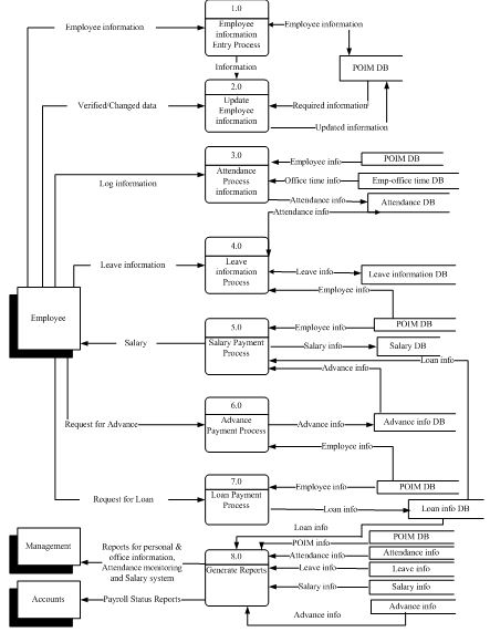
Data Flow Diagrams (DFD) approaches the system from the data aspect. Systems design has borrowed from the traditional approaches of engineering the develop techniques known as structured design. This structured approach allows simple definitions at a high level and leveled definitions at lower levels as necessary. Here I use Gene and Sarson method for DFDs.
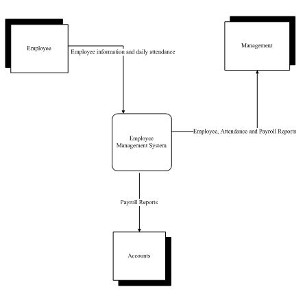
Context level diagram
The context diagrams show the entire system as a single process surrounded by external entities. The major inputs and outputs are represented as data flows.
Definition of a data flow diagram
DFD symbols are:
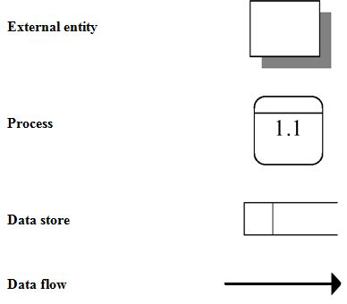
External entity symbol
The fundamental purpose of this symbol, which is either a source of data or a sink is to indicate that, whatever happens at the end of the data flow, it is not the concern of the activities being studied or designed in the DFD. It can be seen from the above example that the way in which a DFD is bounded is shown by the data flowing into the area from the sources and the data flowing out to the sinks. The data flow to or from an external entity crosses the boundary of the area being described. In lower level DFDs it is not necessary to show the sources or sinks of data flows. External entities may be people, departments, functions or other groups external to the area being described by the DFD.
Process symbol
In a DFD the rectangle implies that some activity takes place, transforming the input data in some way to produce the output data. Details of the enquiry are input. These details, together with prices, become the output, the quotation. There must be no increase or decrease in the data as a result of the process. If the total of the inputs does not equal the total of the outputs in all processes, the DFD is incomplete. Any decisions taken are contained within process. There is no separate decision symbol.
Data store symbol
There are only two justifications for stores in any system. One is that data exists which will be required frequently for output, but which would be costly and time consuming to input each time. Therefore reference files are created. The second reason is that data exists which is not required currently by the process but which will be required, either in another process or at a later date. Time-shifting storage files accommodate this requirement. All data store fall into one or both of these categories. This will have some effect on data analysis. When a data store is indicated on a DFD, the flow lines to or from the data store can be of two types. When the data store is used only for reference, the flow line is in one direction from the data store to the process.
Data flow line
No alternation to data can take place within a flow line. The data that leaves one process is exactly that which arrives at the next process. An arrow, usually at the end of the flow line, indicates direction of flow. Sometimes it is convenient to have branching data flows. This may happen when a particular process carries out some work and produces a data output, which is copied to two or more processes.
5.2.1 Context level DFD
5.2.2 System level DFD
5.2.3 Process Decomposition Diagram
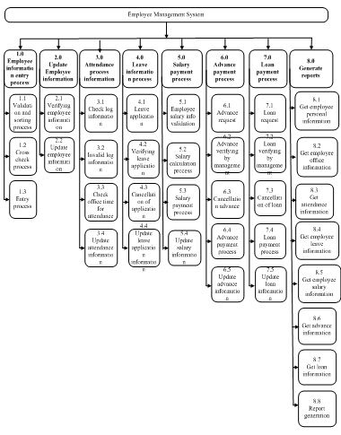
Figure 5.3: Process decomposition diagram for Employee Management System
5.2.4 Level 1 data flow diagrams:
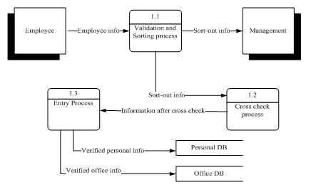
Figure 5.4: Level 1 data flow diagram of Employee information entry process
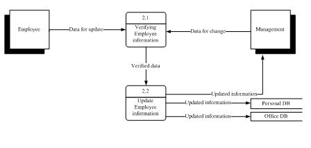
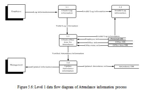

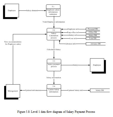

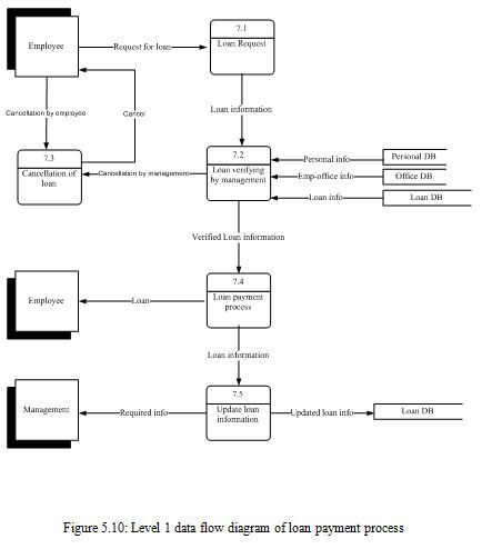
5.3 Data Modeling
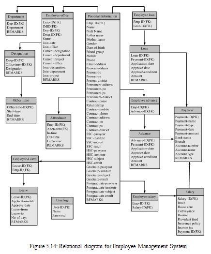
An entity-relationship model is a detailed, logical representation of the data for an organization or for a business area. The E-R model is expressed in terms of entities in the business environment, the relationships (or associations) among those entities, and the attributes (or properties) of both the entities and their relationships. An E-R model is normally expressed as an entity relationship diagram (E-R diagram), which is a graphical representation of an E-R model.
5.3.1 Entity Relationship Diagrams (ERD):
A database system is basically just a computerized record-keeping system. So, it is very important to model the real world in such a way that it can be represented in the computer. Entity-Relationship Model (E-R Model) developed by Peter Chen in 1976 is a very useful tool for modeling the entities and their relationship.
Entity: An entity is a parson, place, object event, or concept in the user environment about which the organization wishes to maintain data.
Theoretically there are 3 types of relationships:
One-to-one
One-to-many
Many-to-many
These relations can be drawn in different ways. Most commonly used drawing technique is using Rectangles for showing Entities and Diamonds for showing the relation among the Entities. There are two types of Entity-Relationship diagram:
Conceptual model
The conceptual model depicts the relationship types between the entities through their many-to-many relations and primary key dependencies.
Physical model
The physical model is the normalized form of the database. The entities and attributes are named according to the user-defined conventions. Each entity holds the names of all their attributes, with underlined attributes as primary keys.
We have used the Logical model to draw the Entity-Relationship diagram.
5.6 Data Dictionary
Data Dictionary provides complete and detail information about the tables and data fields used in the database. It provides information about field name, data type, their size, status and description of the data field. As a part of the System Design Life Cycle (SDLC), this data dictionary contains “Information about data”. It acts as a sophisticated inventory of the database contents. It contains all the data definitions, lists all of the tables, columns & data, records the data domains and maintains the various naming conventions. Here I am presenting data dictionary of the database. Here we have used some fields in the table, which should be clarified. They are-
PK = PRIMARY KEY
FK = FOREIGN KEY
NOT NULL = MANDATORY KEY
Table 5.1:
Entity name: Employee Personal
Table name: Employee Personal
Table function: This table stores the personal information about employee
Field’s description:
Table 5.1:
Entity name: Employee Personal
Table name: Employee Personal
Table function: This table stores the personal information about employee
Field’s description:
Field name | Data type | Length | PK | FK | Not Null | Description |
Emp_ID | Varchar2 | 10 | + | + | Employee’s identity number | |
Name | Varchar2 | 30 | + | Employee name | ||
Nick Name | Varchar2 | 10 | Employee nick name | |||
Father name | Varchar2 | 30 | + | Employee’s father name | ||
Mother name | Varchar2 | 30 | + | Employee’s mother name | ||
Gender | Varchar2 | 10 | + | Employee’s gender | ||
Date-of-birth | Date | + | Employee’s birth day | |||
Blood-group | Varchar2 | 5 | + | Employee’s blood group | ||
Mobile | Varchar2 | 15 | Employee’s mobile number | |||
Phone | Varchar2 | 15 | Employee’s phone number | |||
Email-address | Varchar2 | 30 | Employee’s email address | |||
Present-address | Varchar2 | 50 | + | Employee’s present address | ||
Present-po | Varchar2 | 15 | + | Employee’s present post office | ||
Present-ps | Varchar2 | 15 | + | Employee’s present police station | ||
Present-district | Varchar2 | 15 | + | Employee’s present district | ||
Permanent-address | Varchar2 | 50 | + | Employee’s permanent address | ||
Permanent-po | Varchar2 | 15 | + | Employee’s permanent post office | ||
Permanent-ps | Varchar2 | 15 | + | Employee’s permanent police station | ||
Permanent-district | Varchar2 | 15 | + | Employee’s permanent district | ||
Contract-name | Varchar2 | 30 | + | Employee’s contract name | ||
Relationship | Varchar2 | 15 | + | The relationship between with employee and contract person | ||
Contract-mobile | Varchar2 | 15 | + | Contract person’s mobile number | ||
Contract-phone | Varchar2 | 15 | + | Contract person’s phone number | ||
Contract-address | Varchar2 | 50 | + | Contract person’s address | ||
Contract-po | Varchar2 | 15 | + | Contract person’s post office | ||
Contract-ps | Varchar2 | 15 | + | Contract person’s police station | ||
Contract-district | Varchar2 | 15 | + | Contract person’s district | ||
SSC-passyear | Date | Employee’s SSC pass year information | ||||
SSC-institute | Varchar2 | 30 | Employee’s SSC pass institute | |||
SSC-subject | Varchar2 | 15 | Employee’s SSC subject | |||
SSC-result | Varchar2 | 15 | Employee’s SSC pass result | |||
HSC-passyear | Date | Employee’s HSC pass year information | ||||
HSC-institute | Varchar2 | 30 | Employee’s HSC institute name | |||
HSC-subject | Varchar2 | 15 | Employee’s HSC pass subject | |||
HSC-result | Varchar2 | 15 | Employee’s SSC pass result | |||
Graduate-passyear | Date | Employee’s graduate pass year information | ||||
Graduate-institute | Varchar2 | 30 | Employee’s graduate pass institute | |||
Graduate-subject | Varchar2 | 15 | Employee’s graduate pass subject | |||
Graduate-result | Varchar2 | 15 | Employee’s graduate pass result | |||
Postgraduate-passyear | Date | Employee’s postgraduate pass year information | ||||
Postgraduate-institute | Varchar2 | 30 | Employee’s postgraduate pass institute | |||
Postgraduate-subject | Varchar2 | 15 | Employee’s postgraduate pass subject | |||
Postgraduate-result | Varchar2 | 15 | Employee’s postgraduate pass result | |||
Font-photo | Longraw | Employee’s font photo | ||||
Side-photo | Longraw | Employee’s side photo | ||||
Passport-photo | Longraw | Employee’s passport photo | ||||
REMARKS | Varchar2 | 100 | Any additional information |
Table 5.2:
Entity name: Employee office
Table name: Employee office
Table function: This table stores the office information about employee
Field’s description:
Field name | Data type | Length | PK | FK | Not Null | Description |
Emp_ID | Varchar2 | 10 | + | Employee’s identity number | ||
IMID | Varchar2 | 10 | + | + | Employee’s office identity number | |
Dep-ID | Varchar2 | 10 | + | Department identity number | ||
Desg-ID | Varchar2 | 10 | + | Designation identity number | ||
Status | Varchar2 | 15 | + | Employee status. For example-activate, retired | ||
Join-date | Date | + | Employee join date | |||
Join-office | Varchar2 | 15 | Employee join office | |||
Current-designation | Varchar2 | 15 | + | Employee current designation | ||
Current-department | Varchar2 | 15 | + | Employee current department | ||
Current-project | Varchar2 | 15 | + | Employee current project | ||
Current-office | Varchar2 | 15 | + | Employee current office | ||
Join-designation | Varchar2 | 15 | Employee join designation | |||
Join-project | Varchar2 | 15 | Employee join project | |||
REMARKS | Varchar2 | 100 | Additional information and comments |
Table 5.3:
Entity name: Department
Table name: Department
Table function: This table stores the information about department
Field’s description:
Field name | Data type | Length | PK | FK | Not Null | Description |
Dep-ID | Varchar2 | 10 | + | + | Department identity number | |
Department | Varchar2 | 15 | + | Department name | ||
REMARKS | Varchar2 | 100 | Additional information and comments |
Table 5.4:
Entity name: Designation
Table name: Designation
Table function: This table stores the information about employee designation
Field’s description:
Field name | Data type | Length | PK | FK | Not Null | Description |
Desg-ID | Varchar2 | 10 | + | + | Designation identity number | |
Officetime-ID | Varchar2 | 10 | + | + | Office time identity number | |
Designation | Varchar2 | 15 | + | Designation name | ||
REMARKS | Varchar2 | 100 | Additional information and comments |
Table 5.5:
Entity name: Office-time
Table name: Office-time
Table function: This table stores the information about employee office time
Field’s description:
Field name | Data type | Length | PK | FK | Not Null | Description |
Officetime-ID | Varchar2 | 10 | + | + | Office time identity number | |
Start-time | Date | + | Office start time | |||
End-time | Date | + | Office end time | |||
REMARKS | Varchar2 | 100 |
|
|
| Additional information and comments |
Table 5.6:
Entity name: Attendance
Table name: Attendance
Table function: This table stores the information about employee attendance
Field’s description:
Field name | Data type | Length | PK | FK | Not Null | Description |
Atten-date | Date | + | + | Attendance date | ||
Emp-ID | Varchar2 | 10 | + | + | Employee identity number | |
In-time | Date | + | Employee in time | |||
Out-time | Date | + | Employee out time | |||
Late-cause | Varchar2 | 30 | Late cause | |||
REMARKS | Varchar2 | 100 | Comments |
Table 5.7:
Entity name: Employee-leave
Table name: Employee leave
Table function: This table stores the information about employee leave
Field’s description:
Field name | Data type | Length | PK | FK | Not Null | Description |
Leave-ID | Varchar2 | 10 | + | + | Leave identity number | |
Emp-ID | Varchar2 | 10 | + | + | Employee identity number |
Table 5.8:
Entity name: Leave
Table name: Leave
Table function: This table stores the leave information of employee
Field’s description:
Field name | Data type | Length | PK | FK | Not Null | Description |
Leave-ID | Varchar2 | 10 | + | + | Leave identity number | |
Application-date | Date | + | Leave application date | |||
Approve-date | Date | + | Leave approve date | |||
Leave-from | Date | + | Leave date from | |||
Leave-to | Date | + | Leave date to | |||
No-of-days | Number | (3,0) | + | Number of leave date | ||
REMARKS | Varchar2 | Additional information and comments |
Table 5.9:
Entity name: User log
Table name: User log
Table function: This table stores the user log information
Field’s description:
Field name | Data type | Length | PK | FK | Not Null | Description |
User-ID | Varchar2 | 10 | + |
| + | User identity number |
Name | Varchar2 | 30 |
|
| + | Name of user |
Password | Varchar2 | 10 |
|
| + | User password |
Table 5.10:
Entity name: Employee loan
Table name: Employee loan
Table function: This table stores the information of employee loan
Field’s description:
Field name | Data type | Length | PK | FK | Not Null | Description |
Emp-ID | Varchar2 | 10 |
| + | + | Employee identity number |
Loan-ID | Varchar2 | 10 |
| + | + | Loan identity number |
Table 5.11:
Entity name: Loan
Table name: Loan
Table function: This table stores the loan information
Field’s description:
Field name | Data type | Length | PK | FK | Not Null | Description |
Loan-ID | Varchar2 | 10 | + |
| + | Loan identity number |
Payment-ID | Varchar2 | 10 |
| + | + | Payment identity number |
Application-date | Date |
|
| + | Loan application date | |
Approve-date | Date |
|
| + | Loan approve date | |
Approve-condition | Varchar2 | 100 |
|
|
| Loan approve condition |
Amount | Number | (10,0) |
|
| + | Loan amount |
REMARKS | Varchar2 | 100 |
|
|
| Additional information and comments |
Table 5.12:
Entity name: Employee advance
Table name: Employee advance
Table function: This table stores the information about employee advance
Field’s description:
Field name | Data type | Length | PK | FK | Not Null | Description |
Emp-ID | Varchar2 | 10 |
| + | + | Employee identity number |
Advance-ID | Varchar2 | 10 |
| + | + | Advance identity number |
Table 5.13:
Entity name: Advance
Table name: Advance
Table function: This table stores the advance information
Field’s description:
Field name | Data type | Length | PK | FK | Not Null | Description |
Advance-ID | Varchar2 | 10 | + |
| + | Advance identity number |
Payment-ID | Varchar2 | 10 |
| + | + | Payment identity number |
Application-date | Date |
|
| + | Advance application date | |
Approve-date | Date |
|
| + | Advance approve date | |
Approve-condition | Varchar2 | 100 |
|
|
| Advance approve condition |
Amount | Number | (10,0) |
|
| + | Advance amount |
REMARKS | Varchar2 | 100 |
|
|
| Additional information and comments |
Table 5.14:
Entity name: Employee salary
Table name: Employee salary
Table function: This table stores the information of employee salary
Field’s description:
Field name | Data type | Length | PK | FK | Not Null | Description |
Emp-ID | Varchar2 | 10 |
| + | + | Employee identity number |
Salary-ID | Varchar2 | 10 |
| + | + | Salary identity number |
Table 5.15:
Entity name: Salary
Table name: Salary
Table function: This table stores the salary information
Field’s description:
Field name | Data type | Length | PK | FK | Not Null | Description |
Salary-ID | Varchar2 | 10 | + |
| + | Salary identity number |
Payment-ID | Varchar2 | 10 |
| + | + | Payment identity number |
Basic | Number | (10,2) |
|
| + | Basic amount |
House-rent | Number | (10,2) |
|
|
| House rent amount |
Conveyance | Number | (10,2) |
|
|
| Conveyance amount |
Bonus | Number | (10,2) |
|
|
| Bonus amount |
Provident-fund | Number | (10,2) |
|
|
| Provident fund amount |
Insurance-policy | Number | (10,2) |
|
|
| Insurance policy amount |
Income-tax | Number | (10,2) |
|
|
| Income tax amount |
Table 5.16:
Entity name: Payment
Table name: Payment
Table function: This table stores the payment information
Field’s description:
Field name | Data type | Length | PK | FK | Not Null | Description |
Payment-ID | Varchar2 | 10 | + |
| + | Payment identity number |
Payment-name | Varchar2 | 30 |
|
| + | Payment name |
Payment-type | Varchar2 | 15 |
|
| + | Payment type |
Payment-date | Date |
|
| + | Payment date | |
Payment-amount | Number | (10,2) |
|
| + | Payment amount |
Bank-name | Varchar2 | 30 |
|
|
| Bank name |
Branch | Varchar2 | 15 |
|
|
| Branch name |
Account-number | Varchar2 | 20 |
|
|
| Account number |
Account-name | Varchar2 | 30 |
|
|
| Account name |
Account-type | Varchar2 | 20 |
|
|
| Account type |
REMARKS | Varchar2 | 100 |
|
|
| Additional information and comments |
CHAPTER SIX
SYSTEM DESIGN
Coding is the one of the most important part of software development. Coding is the process of converting the design in to program code or software. It can be considered as to be the heart of the system.
For implementing the coding, I used Oracle Developer to create front-end application, Oracle 8i for the back-end and reporting convention for reporting. The design contains forms – which are connected to database instances and give user all the functionalities and interface to run the software and produce outcomes.
6.1 Input forms:
I have designed the user interface with Oracle 6i form developer. The interface is comprised of some screens, called ‘Form’ here, which provides user visual feedback, interaction medium and performs many complex tasks. There are several forms and reports for different processes.
There are given some sample forms of my software. I want to introduced the form name, reason, using process, working capability and database connection for each form.
The forms are situated from the next pages
Form 1: User log in
Why use the form
This form is used to user login to the software.
How to use the form:
The user who wants to perform any operation or view any report, he/she has to have the permission for that function. Every user should not have permission about use whole software ,they should be restricted for example only the Management has the authority to view a particular report. Every user who is permitted to use the software has a particular user name and password. After opening the software, he/she is shown a login page. Then, he/she has to enter the information of user name and password and then has to press ‘Login’ button.
Figure 6.1: Log in form
Connection with the database
The form will connect to the database system table where the user name and password are stored. Here the name of the table is ‘User Log’.
Form 2: Home Page
Why use the form
This form is used to choose the different portion of the software.
How to use the form:
After logging in successfully, the system will get the defined roles for that user by the
given user name. The user is able to perform any operation according to his/her predefined roles. User can access the data entry portion like ‘Employee information’, ‘Payroll information’ or ‘Attendance logform’ etc. In addition user can use the report link for see the different reports. It is the home page of the software.
Figure 6.2: Home form
Connection to the database
There are no data table connection in this form. This form is the first form menu of the software. And controlled by form link not database. User can access the portion whatever they want to use but every use portion should be authorized.
Form 3: Employee personal entry
Why use the form
This form is used to entry the personal information of the employee.
How to use the form:
User can access the employee personal information by this form. For example He can enter the information about employee name, father name, gender, religion etc. by this form. The user can change the existing information of an employee also. In addition user can delete information. He/she use this form for add a new employee.
Figure 6.3: Employee Personal_info Operate form
Connection with the database
The form will connect to the database system table where the employee personal information are stored. The name of the table is ‘Personal Information’ where this form is connected.
Form 4: Employee office entry
Why use the form
This form is used to entry the office information of the employee.
How to use the form:
User can access the office information of the employee by this form. For example He can enter the information about joining date, joining position, current department, current position etc by this form. The user can change the existing information of an employee also. In addition user can delete information.
Figure 6.4: Employee Office_info Operate form
Connection with the database
The form will connect to the database system table where the employee office information are stored. The name of the table is ‘Employee Office’ where this form is connected.
Form 5: Employee address_info operate
Why use the form
This form is used to entry and operate the address information of the employee.
How to use the form:
User can access the employee address information for employee. For example He can enter the information about present address, present post office, present police station current address, current district etc by this form. The user can change the existing information of an employee address also. In addition user can delete address information.
Figure 6.5: Employee Address info Operate form
Connection with the database
The form will connect to the database system table where the employee address information are stored. The name of the table is ‘Personal Information’ where this form is connected. Actually this table has many attributes so the forms use a portion of attributes of this table.
Form 6: Employee education_info operate
Why use the form
This form is used to entry and operate the education information of the employee.
How to use the form:
User can access the employee education information for employee. For example He can use the information about SSC year, SSC subject result etc by this form. These form maintain information about SSC, HSC, Bachelors and Masters of an employee. The user can change the existing information of an employee address also. In addition user can delete address information.
Figure 6.6: Employee Education_info Operate form
Connection with the database
The form will connect to the database system table where the employee address information are stored. . The name of the table is ‘Personal Information’ where this form is connected.
Form 7: Employee photo_upload form
Why use the form
This form is used to upload the image information of the employee.
How to use the form:
User can access the image information for employee. He/She can performs update operation by this form. Actually this form upload three types of images font, side and passport images of the organization.
Figure 6.7: Employee Image_info Operate form
Connection with the database
The form will connect to the database system table where the employee image information are stored. The name of the table is ‘Personal Information’ where this form is connected.
Form 8: Employee Attendance Log form
Why use the form
This form is used for the attendance login/logout of the employee.
How to use the form:
Employee access the information about their attendance by this form. They can perform login or logout operation at their office in time and office out time respectively. The time of login and logout will provide the operating system to the software. And this will be examined by the attendance report. Management can easily understand the attendance performance of the employees by attendance report.
Figure 6.8: Employee Attendance Login/logout form
Connection with the database
The form will connect to the database system table where the employee attendance information are stored. The name of the table is ‘Attendance’ where this form is connected. Here some attributes are not visible because they are system provided.
Form 9: Employee Leave Application form
Why use the form
This form is used to entry and operate the leave application information of the employee.
How to use the form:
User can access the employee leave application information for employee. User have to entry the from date, to date and leave type and any additional remarks in this form He/She can entry many employees by the ‘Add new’ button. The name, father name, mother name will be provided by the system from employee personal table
Figure 6.9: Employee Leave Application form
Connection with the database
The form will connect to the database system table where the employee leave application information are stored. The name of the tables are ‘Employee personal’,‘Employee leave’ and ‘Leave’ where this form is connected. Here Leave-ID are not visible because they are system provided.
Form 10: Employee Salary_info Operate form
Why use the form
This form is used to entry and operate the salary information of the employee.
How to use the form:
User can access the employee salary information for employee. For example He can enter the information about basic salary, house rent, provident fund ,income tax, etc by this form. The user can delete the existing information of an employee salary also.
Figure 6.10: Employee Salary_info Operate form
Connection with the database
The form will connect to the database system table where the employee salary information are stored. The name of the tables are ‘Employee personal’,’ Employee office’ and ‘Salary’ where this form is connected. Here Salary-ID are not visible because they are system provided. Here the name, designation, department and project are system provided from employee personal and employee office table.
Form 11: Employee Advance_info Operate form
Why use the form
This form is used to entry and operate the advance information of the employee.
How to use the form:
User can access the employee advance information for employee. For example, user can enter the information about basic application date, approve date, amount ,condition by this form.
Figure 6.11: Employee Advance_info Operate form
Connection with the database
The form will connect to the database system table where the employee advance information are stored. The name of the tables are ‘Employee personal’,’ Employee office’ and ‘Advance’ where this form is connected. Here Advance-ID are not visible because they are system provided. Here the name, designation, department and project are system provided from employee personal and employee office table. These are come from the salary form.
Form 12: Employee Loan_info Operate form
Why use the form
This form is used to entry and operate the loan information of the employee.
How to use the form:
User can access the employee loan information for employee. For example, user can enter the information about basic application date, approve date, amount ,condition by this form.
Figure 6.12: Employee Loan_info Operate form
Connection with the database
The form will connect to the database system table where the employee loan information are stored. The name of the tables are ‘Employee personal’,’ Employee office’ and ‘Loan’ where this form is connected. Here Loan-ID are not visible because they are system provided. Here the name, designation, department and project are system provided from employee personal and employee office table. These are come from the salary form.
Form 13: Employee Payment_info Operate form
Why use the form
This form is used to entry and operate the payment information of the employee.
How to use the form:
User can access the employee payment information for employee. For example, user can enter the information about basic payment name, payment type, payment date ,amount, bank name, their branch and another accounts information by this form.
Figure 6.13: Employee Payment_info Operate form
Connection with the database
The form will connect to the database system table where the employee payment information are stored. The name of the tables are ‘Employee personal’,’ Employee office’ and ‘Payment’ where this form is connected. Here Payment-ID are not visible because they are system provided. Here the name, designation, department and project are system provided from employee personal and employee office table. These are come from the salary form. Payment form will be used every time with the salary or advance or loan. So the ‘Salary’,’ Advance’ and ‘Loan’ database are also used here.
6.2 Coding Conventions
In the Forms and Reports development phase, standards for User-Interface designing will be maintained. The different Forms will be designed to look similar and a consistent color scheme will be maintained throughout the various forms. Every attempt will be to emphasize User-friendliness. Wherever possible options will be put in place to reduce or facilitate user input (e.g. drop-down-lists, Combo-boxes, Radio buttons etc.). Hint lines and Tips will also be incorporated with the various Form items. A user-friendly form menu will be developed. In the Coding phase, proper programming practices will be followed in the development of the pl/sql and oracle 6i developer for triggering codes. These include: indentations, comments, variable and object naming etc. Actually the best of us will be in action during this coding period.
CHAPTER SEVEN
TESTING AND CONVERSION
After designing has been completed, the software development entered into testing phase. Testing is the process of exercising a program with the specific intent of finding errors prior to delivery to the end user. Testing involves operation of a system or application under controlled conditions and evaluating the results. The controlled conditions should include both normal and abnormal conditions. Testing should intentionally attempt to make things go wrong to determine if things happen when they shouldn’t or things don’t happen when they should. After testing any software come out in reality.
7.1 Objective
The testing is performed for the purposes as below:
It will uncover potential errors and bug entry points in the software.
It will demonstrate that software functions appear to be working according to specification, that behavioral and performance requirements appear to have been met.
Data collected as testing is conducted provide a good indication of software reliability and indication of software quality as a whole.
The objective is not to show absence of errors and defects, it can only show that software errors and defects are present.
7.2 Test Levels
There are three test levels –
• Unit Test,
• System Test
• Acceptance test.
Here in my project only Unit Testing and System Testing have been performed.
Unit Testing
In unit testing the programs that make up the system were tested. Unit testing focuses first on the independent modules to locate errors. This enabled to detect errors in coding and logic that were contained within that module alone.
System Testing
System testing does not test the software but it also tests the integration of each module of the system. The proposed system too was put through the system test to find any sort of discrepancy, if so exists between the system and its original objective, current specifications and system documentation. But the primary concern was the compatibility of individual modules. To attain perfection some special level system tests were performed after testing the results it was found that the program and the system as a whole meet all the specified requirements.
To perform system testing, we had to integrate the project with an existing system.
7.3 Conversion and Documentation
As my internship period is complete, the development of the software is almost Complete. It had unit testing, as well as system testing. More enhancements, reviews and documentation will fulfill the software development at optimum level.
CHAPTER EIGHT
CONCLUSION
Demand of practical work experience has no other alternative in today’s job market. So before getting into job students should have some real world work experience in major field of study or the career choice that interests him/her. It will open up their eyes and bring new horizon to them. Internship can be defined as a transition from university to real world workplace through some work experience. The whole internship process was an extensive learning phase for me. While working with the project, I came across with various problems and solving the problems has indeed helped a lot to broaden my knowledge. I had no previous experience of designing this kind of software. So after being assigned for the job of designing Employee Management System at DIGITAL ARCHITECTS LIMITED, it was indeed very challenging for me. But the overall work to be done was only possible due to the kind assistance of few wonderful people. All though the whole development process I got the chance to implement my theoretical knowledge of computer science I learnt over last four years into practice. Not only that, through report writing I got to know how to compose professional and formal reports for any project works. These will help me a lot in future not only while working in industries but also in higher studies. I did not add the production planning, store and accounts info data in that system. In future it can easily add because the system is deigned that in such a way that any one can add this when it is need. Lastly, again I am grateful to IUB for giving me this opportunity to conduct my internship.
