ABSTRACT
Material science, packaging concepts, fabrication technology and novel cooling strategies are some of the key areas requiring synchronal research for successful thermal management. This thesis attempts to describe the heat transfer characteristics of closed loop pulsating heat pipes (CLPHPs). These apparently simple looking devices are extremely intriguing for theoretical and experimental investigations. It is rare to find a combination of such events and mechanisms, like bubble nucleation/collapse and agglomeration, bubble pumping action, pressure/temperature perturbations, flow regimes changes, dynamic instabilities, metastable non-equilibrium conditions, flooding/bridging etc., all together contributing towards the thermal performance of the device. This performance characterization has been done for water as working fluid with different filling ratios and different inclination angles of the heat pipes. This experimental result indicates an influence of buoyancy and gravity force of the working fluid on the performance of the CLPHP. The experiment is conducted on a PHP made of copper capillary tube of 2.2-mm inner diameter. The results demonstrate the effect of heat input and volumetric filling ratio of the working fluid on the thermal performance of the device.
INTRODUCTION
MOTIVATION
Meandering tube pulsating heat pipes, (PHPs) have already been found some applications in micro-processor and power electronics applications owing to favorable operational characteristics coupled with relatively cheaper costs. Although grouped as a subclass of the overall family of heat pipes, the subtle complexity of thermo-fluidic transport phenomena is quite unique justifying the need of a completely different research outlook. Comprehensive theory of operation and reliable database or tools for the design of PHPs according to a given micro-electronics-cooling requirement is still an unrealized task. A closed loop pulsating or oscillating heat pipe consists of a metallic tube of capillary dimensions wound in a serpentine manner and joined end to end. It is first evacuated and then filled partially with a working fluid, which distributes itself naturally in the form of liquid–vapor slugs and bubbles inside the capillary tube. Respective tube sections thus have a different volumetric phase distribution. One end of this tube bundle receives heat transferring it to the other end by a pulsating action of the liquid–vapor slug-bubble system. There may exist an optional adiabatic zone in between. This type of heat pipe is essentially a non-equilibrium heat transfer device. The performance success primarily depends on continuous maintenance or sustenance of these non-equilibrium conditions in the system. The liquid and vapor slug/bubble transport is caused by the pressure pulsations inside the device. Since these pressure pulsations are fully thermally driven, because of the inherent construction of the device, there is no external mechanical power source required for the fluid transport.
In a working PHP, there exist temperature gradients between the evaporator and the condenser section. These are coupled with inherent real-time perturbations, due to:
- local non-uniform heating and cooling within the evaporator and condenser tube sections,
- unsymmetrical liquid–vapor distributions causing uneven void fraction in the tubes, and,
- presence of approximately triangular or saw-tooth alternating component of pressure drop superimposed on the average pressure gradient in a capillary slug flow due to the presence of vapor bubbles.
The net effect of all these temperature gradients and perturbations is to create a non-equilibrium pressure condition which, in conjunction with the non-uniform void fraction distribution in respective tubes, as stated earlier, is the primary driving force for thermo fluidic transport. Thus self-sustained thermally driven oscillations are obtained.
OBJECTIVES
The main objectives of this experiment are
- To understand the different operational regimes (evaporator, adiabatic and condenser section) of closed loop pulsating heat pipe.
- To compare the thermal resistance of heat pipe for different orientation of heat pipe
- To compare the thermal resistance at different filling ratio
- To study the evaporator and condenser temperature of heat pipe at different orientation
Historical Development
Historically, the first application of gravity heat pipes was in boilers and bakeries, the so-called Perkins tube was widely used in the 19th century. This is a bare, thick-walled carbon steel tube filled with a certain amount of water, about 1/3 of the total tube volume, and hermetically sealed. The lower tube end was heated by flue gases, the upper end extended into the boiler where it was used to generate steam.
In 1938 a patent was granted in the USA which describes a tube incorporating capillary grooves to aid liquid distribution and hence vaporization in boilers. The first patent of a heat pipe employing a capillary wick for pumping liquid against gravity was applied by Gaugler in 1944 as a two-phase heat transport device for refrigerators. It was supposed to allow movement of the working fluid without pumps and without natural convection, by utilization of the capillary force generated by a capillary wick.
The heat pipe concept was first put forward by R.S.Gaugler of the general Motors Corporation, Ohio, and USA. In a patent application dated December 21st, 1942, and published as US Patent No. 2350348/ on June 6th, 1944, the heat pipe is described as applied to a refrigeration system.
According to Gaugler, the object of the invention was to “cause absorption of heat, or in other words, the evaporation of the liquid to a point above the place where the condensation or the giving off of heat takes place without expending upon the liquid any addition work to lift the liquid to an elevation above the point at which condensation takes place”. A capillary structure was proposed as the means for returning the liquid from the condenser to the evaporator, and Gaugler suggested that one form this structure might take would be a sintered iron wick. It is interesting to note the comparative small portion of the tube cross section allocated to vapor flow in his designs.
The first heat pipe that Grover built used water as the working fluid and was followed shortly by a liquid sodium heat pipe for operation at 1100 K. Both the high temperature and ambient temperature regime soon explored by many workers in the field. It was until 1966 that the first cryogenic heat pipe was developed by Haskin of the Air Force Flight Dynamic Laboratory at Wright- Patterson Air Force Base.
Between 1964 and 1966, RCA (Radio Corporation of America) was the first corporation to undertake research and development of heat pipes for the commercial application. The concept of Variable conductance or Temperature Controlled Heat pipe was first described by Hall of RCA in a patent application dated October 1964. However, although the effect of a non-conducting gas was shown in Grover’s original publication, its significance for achieving variable conductance was immediate recognized. In subsequent years the theory and technology of variable conductance Heat Pipes was greatly advanced, notably by Bienert and Brennan at Dynatherm and Marcus at TRW. On April 5, 1967, the first “zero g” demonstration of a heat pipe was conducted by a group of engineers of the Los Alamos scientific Laboratory. This first successful flight experiment overcame the initial hesitation that many spacecraft had for using this new technology to solve ever- present temperature control problems on spacecraft. Subsequently, more and more spacecrafts have relied on heat pipes either to control the temperature of individual components or of the entire structure. Some examples of this trend were the ARS- E, OAO, ATS Fand G spacecrafts and the sky labs.
The development of terrestrial applications of heat pipes progresses at much slower pace. In 1968, RCA developed a heat pipe heat sink for transistors used in aircraft transmitters. This probably represented the first commercial application of heat pipes.
Publications in 1967 and 1968 by Feldman, Eastman, and Katzoff first discussed applications of heat pipes to areas outside of government concern and that did not fall under the high temperature classification such as: air conditioning, engine cooling and electronics cooling. These papers also made the first mentions of flexible, arterial, and flat plate heat pipes. 1969publications introduced the concepts of rotational heat pipe with its application to turbine blade cooling and the first discussions of heat pipe applications to cryogenic processes.
EXPERIMENTAL METHOD
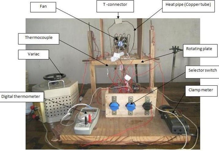
In order to study the heat transfer characteristics of pulsating heat pipe, an experimental facility has been designed, fabricated and installed. The detailed description of experimental apparatus and procedure are presented in the subsequent sections of this chapter.
Experimental Apparatus
- Pulsating Heat Pipe
- Working Fluid (Water)
- Test Stand
- Heating Apparatus
a) Power Supply Unit
b) Ni-Cr Thermic Wire
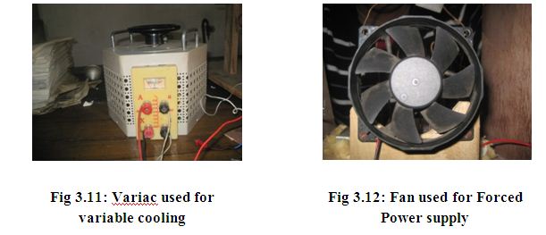
c) Variac
- Cooling Apparatus
a) Battery Fan
b) Adapter Circuit
- Measuring Apparatus
a) Thermocouple K Type
b) Selector Switch
c) Digital Thermometer (Y Type)
Pulsating Heat Pipe
A closed loop pulsating heat pipe or oscillating heat pipe consists of a metallic tube of capillary dimensions wound in a serpentine manner and joined end to end. It consists of 3 sections. They are:
- Evaporator Section
- Adiabatic Section
- Condenser Section
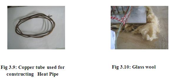
Evaporator Section:
It is the section of the heat pipe where the refrigerant (water) absorbs heat and evaporates. It is located on the bottom section of the heat pipe .The heat is supplied on the heat pipe by nicrome wire which is connected to the variac. as the copper tube is good conductor of electricity so it is not directly connected with nicrome wire because it can make short circuit. So, the nicrome wire is surrounded to a mica sheet and kept in a distance of copper tube. Glass wool is kept between the mica sheet and the copper tube. So, the heat is transferred to the copper tube through the glass wool.
Condenser Section:
It is the section of heat pipe where heat is rejected from the working fluid on this section the working fluid condenses and rejects the same amount of heat which it absorbed from the evaporator section. On this experiment it is located on upper section of the heat pipe.
Adiabatic Section:
It is located between the evaporator section and condenser section. In here the liquid and vapor phases of the fluid flow in opposite directions and no significant heat transfer occurs between the fluid and surrounding medium.
Table : Experimental Parameter and Their Ranges
Parameters | Condition |
| Inner diameter | 2.2 mm |
| Outer diameter | 2.3 mm |
| Total length | 155 mm |
| Length of evaporator section | 30mm |
| Length of adiabatic section | 75mm |
| Length of condenser section | 50mm |
| Material | Copper |
| Air flow rate | 3.5 m/s |
Working Fluid
For choosing the right working fluid some properties have to be considered. They are:
- High value of (dP/dT) at saturation temperature
- Low dynamic viscosity
- Low latent heat
- High specific heat
- Low surface tension
In this experiment water (H₂O) IS used as working fluid. The thermophysical properties are
Test Stand
The test stand is a wooden structure which holds the heat pipe .It has a base where an aluminum box is located. It contains the evaporator section of the heat pipe .the evaporator section is connected to Ni –Cr themic wire which is connected with the variac . The test stand can be rotated and can be kept on any different orientation between horizontal and vertical position. The whole structure is supported by two columns which are situated in a large wooden base.
Heating Apparatus
Variac
Table : Variac specification
| Type: | 3ф |
| Rated capacity: | 300 volt |
| Rated frequency: | 60 Hz |
| Input voltage: | 220 volt |
Power Supply Unit
Type: AC
Voltage: up to 220 volt
Frequency: 50 Hz
Ni-Cr Thermic wire
Diameter: 0.051 inch
Power: 120 W
Cooling Apparatus
Fan
For cooling the working fluid, forced convection is used. For forced convection a D.C fan is used. It is located on test stand in front of the heat pipe.
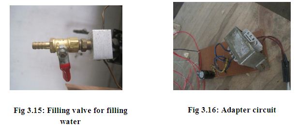
Adapter Circuit
As the fan is a DC fan and the power supply is AC. So, for running the fan a converter circuit is required to convert the AC current to DC current. It consists of a transformer, full wave rectifier circuit to convert the AC to DC current.
Measuring Apparatus
Thermocouple
A number of thermocouple is glued to the wall of pulsating heat pipe. They are calibrated and connected to different sections of heat pipe for measuring temperature. This thermocouple is Ty (Chromel/Alumel) Type K. It is ‘general purpose’ thermocouple. It is low cost and, owing to its popularity, it is available in a wide variety of probes. Thermocouples are available in the -200°C to +1200°C range. Sensitivity is approx 41uV/°C. Use type K unless you have a good reason not to.
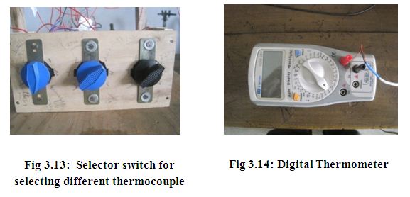
Selector Switch
Selector switch is a type of rotating connector. That can be rotate to different positions to make contact with the particular position of the heat pipe through the thermocouple. For this experiment three selector switches are used. Each of them has 8 points and used to measure the temperature of different points in heat pipe.
Digital Thermometer
Table: Specification of digital thermometer
| AC voltage | 2V 20V 200V 750V |
| DC current | 2 mA, 20 mA, 200 mA |
| Resistance | 200 Ώ -200M Ώ |
| Frequency | 20khz |
Experimental setup
For studying the thermal characteristics of heat pipe, an experimental setup has been built. It is made by a circular copper tube. Its outer diameter is 2.3 mm and inner diameter is 2.2 mm. The total length of this pipe is 155 cm. The tubes are bent to U shape. Two of the extreme bents are connected by a T connector. This forms the closed loop heat pipe whether the open loop heat pipe has no connection between the two extreme ends. For pulsating action of this heat pipe distinct liquid slug and bubble formation are essential. This liquid slug and bubble formation are related to the Eotvos number or Bond number. Eotvos number may be regarded as proportional to buoyancy force divided by surface tension force.
Eo = Eotvos number.
Δρ = Change of density.
σ = Surface tension.
L – Characteristics length.
Selecting the perfect diameter
There is a critical diameter above which the heat pipe will not function as pulsating heat pipe. This critical diameter is related to Eotvos number. For pulsating action the Eotvos number has to be less than or equal to 4.For selecting the inner diameter of heat pipe, the working diameter should be less than the critical diameter. In this experiment the diameter of the heat pipe has been taken 2.2 mm which makes the Eotvos number less than 4.
Number of turns
The number of turns increases the level of perturbations inside the device. If the number of turns is less than a critical value, then there is a possibility of a stop-over phenomenon to occur. As the thermal performance of heat pipe is a function of number of turns, so this has to be selected properly. On this experiment the number of turns of heat pipe is ten (10) which is a optimum number for this diameter and corresponding working fluid.
Selection of working fluid
Working fluid is very important part of heat pipe performance. In this experiment water is used as the working fluid which posses all the characteristics of a good working fluid such as high latent heat, high thermal conductivity, high specific heat and high surface tension.
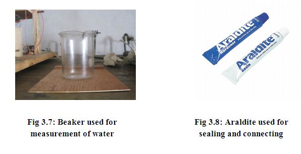
Filling process
In this experiment, water is selected as the working fluid. The filling process is done by using the filling valve which is known as T connector [fig: 3.15]. The liquid filling can be done by different processes. In this experiment the filling process is done by making the pressure difference at the two ends of the pipe. Due to some technical problem t the filling ratio could not be controlled at desired level.
For 450 inclinations the filling ratio is 85.6% and for horizontal position (900 inclinations) the filling ratio is 85%.
Heating process
Heating process is done at the evaporator section. It is situated at the bottom of the heat pipe. The heating process is done by passing the AC current through the nichrome wire. As the resistance of the wire is very high, heat is generated during the current flow. This heat is passed to water and the water is evaporated when the evaporator temperature is higher than the vaporization temperature of water.
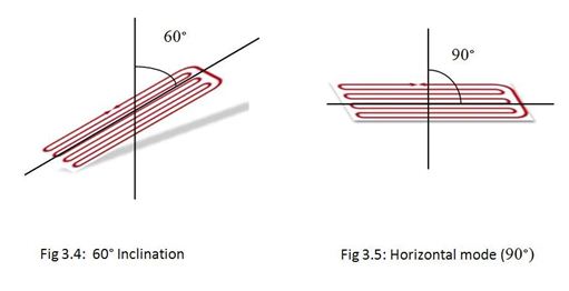
Orientation
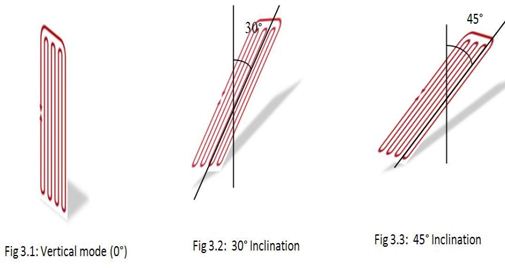
The heat pipe is tilted by changing the angle of the rotating plate of the test stand. Different thermal characteristics are observed on different orientation of heat pipe by changing the tilt angle of this plate. The different orientation angles are:
- Vertical orientation (00)
- 300, 450 and 600 inclinations
- Horizontal orientation (900)
Fig 3.1 to 3.5 show the different orientation of heat pipe and fig to shows the various components and essential apparatus to conduct the experiment.
RESULTS AND DISCUSSION
To evaluate and understand the heat transfer characteristics of closed loop pulsating heat pipe, the wall temperature at different points of the CLPHP is measured. The temperature profiles are plotted against the heat input and time. By using equation (1), thermal resistance is determined and then thermal resistances are plotted against heat input.
Vertical Mode
In vertical mode, the vapor bubbles take up heat in the evaporator and grow in size. Their own buoyancy helps them to rise up in the tube section. Simultaneously other bubbles, which are above in the tube, are also helped by their respective buoyant forces. These rising bubbles in the tube also carry the liquid slugs trapped in between them. In this mode of operation there is a natural tendency for the liquid slugs to travel toward the evaporator helped by gravity force. Simultaneously the vapor bubbles have the natural tendency to travel towards the condenser helped by buoyant force.
Fig 4.1 shows that the thermal resistance of the PHP decreases with the increase of the heat input. At 100% filling ratio, PHP acts as single phase buoyancy driven thermosyphon. In this case, there is no bubble formation and the liquid starts circulating inside the device due to density difference associated with the temperature gradient. So decreasing trend is higher till the heat input of 35 W and then with the increase of heat input the temperature difference does not change much between evaporator and condenser due to higher buoyancy force is required to overcome the liquid phase. So the trend remains nearly steady.
Fig 4.2, with 100% filling ratio, shows that the average evaporator and condenser temperature increase with the heat input. At 100% filling ratio the maximum temperature 101.78⁰ C is attained at 56.67 W heat input. The maximum condenser temperature 46.24⁰ C is attained at same heat input and time. In this figure the slope of evaporator temperature is higher than the slope of condenser temperature.
With 82.5% filling ratio, small amount of bubble formation occurs and natural circulation of flow is hindered. Evaporator temperature increases which results high temperature difference between evaporator and condenser. Fig 4.3 shows that the slope of decreasing trend of thermal resistance is higher till the heat input of 12 W. Bubble formation increases with heat input leading to higher pumping pressure and thermal instabilities. Then the pulsating mode starts and thermal resistance decreases smoothly.
Fig 4.4, with 82.5% filling ratio, shows that the average evaporator and condenser temperature increase with the heat input. At 82.5% filling ratio the maximum temperature 101.39⁰ C is attained at 62.31 W heat input. The maximum condenser temperature 56.53⁰ C is attained at same heat input.
Fig 4.5, with 63% filing ratio, shows that the thermal resistance of the PHP decreases with the increase of the heat input. At this filling ratio the partial dry out of evaporator section occurs and the true pulsating mode of PHP starts. The performance of the CLPHP improves. The pulsating action starts properly and the thermal resistance is expected to decrease smoothly. But the curve does not show the smooth trend due to the entrapped air in the heat pipe which enters during the filling process.
Fig 4.6, with 63% filling ratio, shows that the average evaporator and condenser temperature increases with the heat input. At 63% filling ratio, the maximum temperature 102.67⁰ C is attained at 62.81 W heat input. The maximum condenser temperature 61.56⁰ C is attained at same heat input.
At 41.3% filling ratio, the dry out of evaporator section increases. So, the bubble formation increases and the pumping action improve. So, the figure 4.7 shows that the decreasing trend of thermal resistance is almost smooth throughout the heat input.
Fig 4.8, with 41.3% filling ratio, shows average evaporator and condenser temperature increases with the heat input. At 41.3% filling ratio, the maximum temperature 102.43⁰ C is attained at 64.27 W heat input. The maximum condenser temperature 62.83⁰ C is attained at the same heat input.
At 28% filling ratio, the internal bubble size increases in the evaporator which creates the dry out of evaporator section. The flow instabilities increase the level of perturbation. So, the decrement of thermal resistance is high. Fig 4.9, with 28% filing ratio, shows that the decreasing trend of thermal resistance higher till the heat input is 20 W and than the decreasing trend becomes slow. The maximum performance is observed at this filling ratio.
Fig 4.10, with 28% filling ratio, shows that the average evaporator and condenser temperature increase with the heat input. At 28% filling ratio the maximum temperature 104.01⁰ C is attained at 63.36 W heat input. The maximum condenser temperature 72.41⁰ C is attained at same heat input.
Fig 4.11 shows that horizontal mode (90⁰ inclinations) of operation with 82% filling ratio. It shows the thermal resistance of the PHP nearly steady with the heat input. This suggests that gravity force is uniform throughout the PHP. So, the gravity force is inactive and the only dominating force is surface tension. At horizontal inclination (90°), all the temperatures of the adiabatic section rapidly become equal and there is no movement of bubble plugs. Bubbles only oscillate about a mean position with high frequency. The temperature difference between the evaporator and condenser increases with the increment of heat input proportionally so the thermal resistance remains nearly steady.
Fig 4.12, at horizontal inclination with filling ratio 82%, shows that average evaporator and condenser temperature increase with the heat input. At 82% filling ratio, the maximum temperature 101.87⁰ C is attained at 40.92 W heat input. The maximum condenser temperature 48.42⁰ C is attained at same heat input.
At 60⁰ inclination with 79% filling ratio, the pressure force is created due to the temperature difference between the evaporator and condenser. The pressure force acts with the surface tension force inside the tubes. At first the bubbles move slowly to condenser, then the bubbles move faster with the increase of heat input, so the heat transfer increases and Fig 4.13 shows that the thermal resistance of the PHP decreases with increase of heat input.
Fig 4.14, at 60⁰ inclination with filling ratio 79%, shows that the average evaporator and condenser temperature increase with the heat input. At 79% filling ratio, the maximum temperature 104.57⁰ C is attained at 56.78 W heat input. The maximum condenser temperature 57.44⁰ C is attained at same heat input.
Fig 4.15, 45⁰ inclination of with 85.6% filling ratio, shows that the thermal resistance of the PHP decreases with increase of heat input. Before 30W heat input the decrease trend of thermal high and after that the decrease trend becomes slow.
Fig 4.16, at 45⁰ inclination with filling ratio 85.6%, shows that the average evaporator and condenser temperature increase with the heat input. At 85.6% filling ratio, the maximum temperature 103.54⁰ C is attained at 58.68 W heat input. The maximum condenser temperature 61.08⁰ C is attained at same heat input.
Fig 4.17, 30⁰ inclination with 79% filling ratio, shows that the decreasing trend of the thermal resistance of the PHP is uniform throughout the heat input. At this position the pressure force due to temperature difference is higher than the gravity force. The surface tension force is also active.
Fig 4.18, at 30⁰ inclination with filling ratio 79%, shows that the average evaporator and condenser temperature increase with the heat input. At 79% filling ratio, the maximum temperature 104.74⁰ C is attained at 61.23 W heat input. The maximum condenser temperature 64.33⁰ C is attained at same heat input.
Fig 4.19 shows that the comparison of thermal resistance vs. heat Input at different filling ratios. A closer look at comparison curve, it has been found that in between 25% and 65% filling ratio, the PHP functions in a true pulsating mode. Thermal performance improves at lower filling ratio with partial or total dry out in the evaporator section. The maximum performance was observed at about 25% to 30% filling ratio.
Fig 4.20 shows that the maximum heat input vs. filling ratio. The maximum heat input was found at lower filling ratio and minimum heat input at 100% filling ratio. At 100% filling ratio, the buoyancy induced natural liquid circulation. Liquid circulation gets hampered due to surface tension which results insufficient perturbations. So the performance of the device is hampered. But at lower filling ratio, more bubbles are formed which produce more perturbations. The PHP operates as true pulsating mode and give high throughput.
Fig 4.21 shows that comparison of thermal resistance vs. heat input at different inclination nearly same filling ratio. A closer look at comparison curve, at 30⁰ inclination closed loop PHP performs better than other position but comparatively at vertical mode of operation it gave maximum heat throughput.
Fig 4.22 shows that the maximum heat input vs. inclination angle nearly at same filling ratio. The maximum heat input decreases with decreasing the inclination angle. The maximum heat input was obtained at vertical inclination (0°) and minimum heat input was obtained at horizontal position (90°). At vertical inclination, the motion of the liquid slugs and vapor bubbles at one section of the PHP moves toward the condenser. This works as driving force. On the other section the motion of slugs and bubbles moves toward the condenser. This works as restoring force. The inter-play between the driving force and restoring force leads to oscillation of the vapor bubbles and liquid slugs in the axial direction. So heat input is high at vertical position. At horizontal inclination (90°), all the temperatures of the adiabatic section rapidly equalize and no movement of bubble plugs. Bubbles only oscillate about a mean position with high frequency. The input heat has to be stopped for safety and surface tension predominates in capillary dimensions of the tubes.
From all the curves, some deviations are found from the expected theoretical value. During the filling of working fluid, theoretically the tube must be vacuumed perfectly. But due to technical limitations, the tubes could not be maintained vacuumed. Some air infiltrated in the heat pipe. So, during heating the entrapped air is also heated with the working fluid and the resistance of the air cannot be neglected. So, the actual thermal resistance is greater than expected theoretical value.
SUMMARY AND CONCLUSION
The following facts summarize the essential aspects of this study:
1. Valuable information related to the fundamental characteristics and operational regimes of a PHP were generated. An operationally better performance and self-sustained thermally driven pulsating action of the device was only observed in the filling ratio range 25–65%. Above this range, the overall degree of freedom and the pumping action of bubbles were insufficient for rendering good performance. Below a certain range of filling ratio, partial dry out of the evaporator was detected.
2. The results also indicate that a 100% filled PHP (not working in the pulsating mode but instead as a single-phase buoyancy-induced thermosyphon) is thermally better performing than a partially filled pulsating mode device under certain operating conditions.
3. The tested PHP did not operate in the vertical mode constantly for the working fluid tested. The reasons are attributed to fixed number of turns and atmospheric pressures existing at testing conditions.
4. Although the Eotvos number of water was much below the prescribed maximum limit of Eo = 4, gravity forces were definitely seen to affect the performance. This suggests that, in the vertical mode fluid transport is mainly by the bubble pumping action thereby providing substantial heat transfer.
5. Closed loop pulsating heat pipes are complex heat transfer systems with a very strong thermo- hydrodynamic coupling governing the thermal performance.
6. Different heat input to these devices give rise to different flow patterns inside the tubes. This intern is responsible for various heat transfer characteristics. The study indicates that design of these devices should aim at thermo-mechanical boundary conditions which resulting convective flow boiling conditions in the evaporator leading to higher local heat transfer co-efficients.
7. The inclination operating angle changes the internal flow patterns thereby resulting in different performance levels. The best performance is obtained from vertical direction and the worst performance is obtained from the horizontal orientation.
RECOMMENDATIONS
- A comprehensive investigation can be carried out on the closed loop heat pipe by changing the filling ratio, working fluid, cross sections, shape and using stainless steel and aluminum.
- Further investigation can be carried out on closed loop pulsating heat pipe by introducing more angle of inclination with different filling ratios.
- Air velocity should be varied to test the thermal performance and water cooling can be incorporated for the comparison of heat transfer performance between water cooling and air cooling.
- For accuracy, temperature reading should be taken electronically via interfacing system with real time data acquisition.
- Room temperature should be controlled and atmospheric properties should be uniform.
- A Computational Fluid Dynamics (CFD) analysis can be done to investigate the reasons of difference in thermal resistance.