Electronic-hydraulic analogies are the modeling of electronic circuits by hydraulic circuits. Because the electric current is unseen and the mechanisms at work in electronics are frequently difficult to illustrate, the various electrical components are represented by hydraulic counterparts. It is also known as hydraulic-electronic analogies. It is a method of modeling and evaluating dynamic systems in engineering, particularly in electrical and fluid systems, by drawing parallels between the behavior of electrical circuits and hydraulic systems.
Electricity (together with heat) was initially thought to be a type of fluid, and the names of many electric numbers (such as current) are taken from hydraulic equivalents. These parallels are useful for understanding and solving problems in both domains, and they have applications in a variety of fields, including control systems, electronics, and fluid dynamics.
The most often used analogy for “electron fluid” in a metal conductor is the electronic-hydraulic analogy (derisively referred to as the drain-pipe theory by Oliver Lodge). As with other analogies, it requires an intuitive and competent comprehension of the underlying paradigms (electronics and hydraulics), and in the case of the hydraulic analogy for electronics, students frequently lack this expertise.
Here’s a basic overview of the key analogies:
(a) Voltage-Pressure Analogy:
- In the electrical domain, voltage represents the driving force behind current flow through a resistor.
- In the hydraulic domain, pressure represents the driving force behind the flow of fluid through a pipe or component.
- Thus, voltage (V) is analogous to pressure (P).
(b) Current-Flow Analogy:
- In the electrical domain, current represents the flow of electric charge through a conductor.
- In the hydraulic domain, flow rate represents the rate of flow of fluid through a pipe.
- Thus, current (I) is analogous to flow rate (Q).
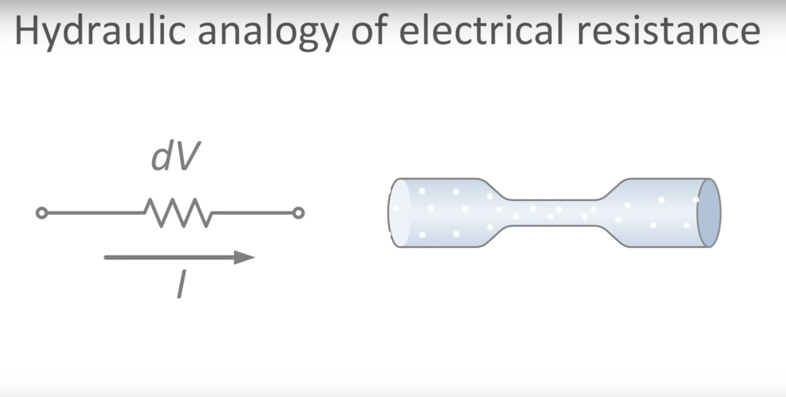
(c) Resistance-Resistance Analogy:
- In the electrical domain, resistance (R) opposes the flow of current in a circuit.
- In the hydraulic domain, resistance (R) opposes the flow of fluid through a pipe.
- Thus, electrical resistance (R) is analogous to hydraulic resistance (also denoted as R or sometimes called “friction”).
(d) Capacitance-Compliance Analogy:
- In the electrical domain, capacitance (C) stores electrical charge and opposes changes in voltage.
- In the hydraulic domain, compliance (C) stores fluid and opposes changes in pressure.
- Thus, electrical capacitance (C) is analogous to hydraulic compliance (C).
(e) Inductance-Inertia Analogy:
- In the electrical domain, inductance (L) opposes changes in current flow.
- In the hydraulic domain, inertia (L) opposes changes in flow rate.
- Thus, electrical inductance (L) is analogous to hydraulic inertia (L).
Engineers and scientists can use analogies to apply principles and techniques from one domain to another. Electrical circuit analysis techniques, such as Kirchhoff’s laws, can be used to study hydraulic systems, and vice versa. This crossover is especially beneficial for building control systems where electrical components may be used to control hydraulic systems or vice versa, such as hydraulic actuators in industrial automation.