A distributed-element filter is an electronic filter in which the elements of the circuit (capacitance, inductance, and resistance) are not localized in discrete capacitors, inductors, and resistors as they are in conventional filters. Its purpose is to allow some signal frequencies to pass while blocking others. Conventional filters are made of inductors and capacitors, and the circuits they create are described by the lumped element model, which considers each element to be “lumped together” in one location. That model is conceptually simple, but as the frequency of the signal increases, or equivalently as the wavelength decreases, it becomes increasingly unreliable.
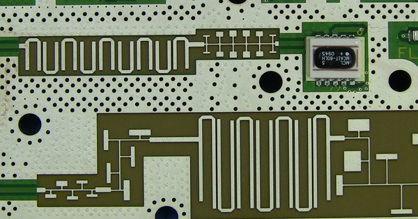
In contrast to lumped-element filters, which use discrete components concentrated in a single area, distributed-element filters distribute the filtering elements throughout the circuit. This filter type is commonly used in high-frequency applications where traditional lumped-element filters are impractical due to their limitations. Transmission lines are the primary filtering elements in distributed-element filters. Microstrip lines, striplines, waveguides, and other types of transmission media can be used to implement these transmission lines. Because these transmission lines are distributed, the filtering action can occur over a wide frequency range.
The ability of distributed-element filters to handle high frequencies with minimal loss and distortion is their primary advantage. As a result, they are well suited for use in telecommunications, radar systems, RF and microwave circuits, and other high-frequency applications. Distributed-element filters achieve high performance in terms of insertion loss, selectivity, and impedance matching by distributing the filtering elements.
The distributed-element model is used in transmission-line theory and applies to all frequencies; many distributed-element components are made of short lengths of transmission line. The elements in the distributed view of circuits are distributed along the length of conductors and are inextricably mixed together. The design of a filter is typically concerned only with inductance and capacitance, but due to the mixing of elements, they cannot be treated as separate “lumped” capacitors and inductors. Although there is no specific frequency above which distributed element filters must be used, they are most commonly associated with the microwave band (wavelength less than one metre).
The distributed bandpass filter is a common type of distributed-element filter. It is made up of a series of resonant sections, each tuned to a different frequency. Transmission lines connect these resonant sections, allowing for the desired bandpass characteristics. Low-pass filters, high-pass filters, and bandstop filters are examples of distributed-element filters.
Distributed-element filters are used in many of the same applications as lumped-element filters, such as radio channel selectivity, noise bandlimiting, and multiplexing multiple signals into one channel. With the exception of high-pass, which is usually only approximated, distributed-element filters can be built to have any of the bandforms possible with lumped elements (low-pass, band-pass, etc.). A distributed-element approach can be used to implement all filter classes used in lumped element designs (Butterworth, Chebyshev, and so on).
A solid understanding of transmission line theory, impedance matching, and filter design techniques is required when designing distributed-element filters. To aid in the design process, advanced simulation tools and computer-aided design (CAD) software are frequently used.
Overall, distributed-element filters achieve the desired filtering characteristics by leveraging the distributed nature of transmission lines.