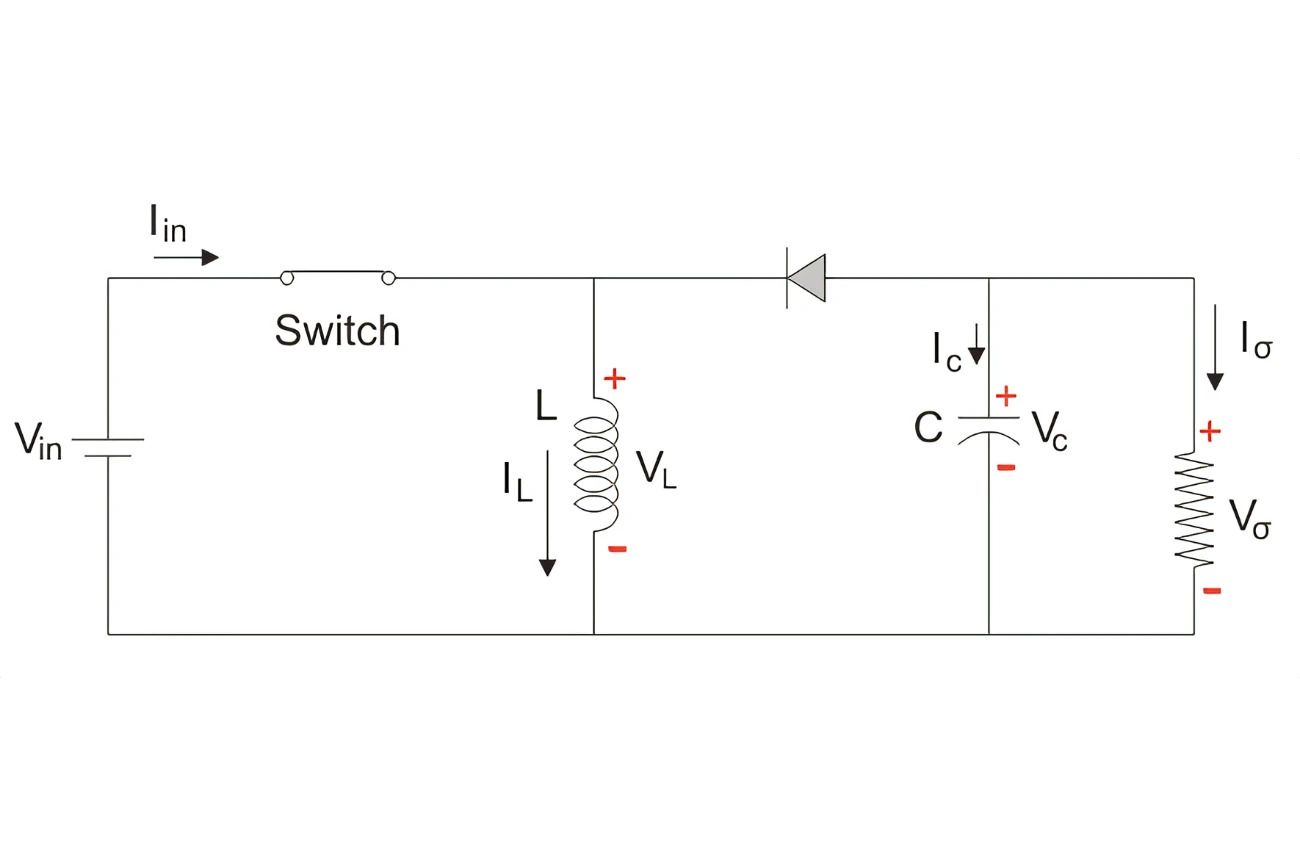
A buck-boost converter is a DC-DC converter circuit that can efficiently increase (boost) or decrease (buck) a DC voltage. It has an output voltage magnitude that is either bigger or smaller than the input voltage magnitude. It is equivalent to a flyback converter that uses a single inductor rather than a transformer. The term “buck-boost converter” refers to two separate topologies. Both may generate a wide variety of output voltages, from significantly higher (in absolute magnitude) than the input voltage to nearly zero. It’s a versatile power electronics device that’s widely employed in a variety of applications, including battery-powered systems, renewable energy systems, and LED drivers.
In the inverting topology, the output voltage has the opposite polarity as the input. This switched-mode power supply has a circuit architecture similar to the boost converter and buck converter. The output voltage is variable depending on the duty cycle of the switching transistor.
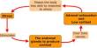
Here’s how it works:
- Buck Mode: When the input voltage is higher than the output voltage, the converter operates in buck mode. In this mode, the input voltage is switched across an inductor, and the output voltage is regulated by controlling the duty cycle of the switching signal. The output voltage is lower than the input voltage, and the current flows through the load.
- Boost Mode: When the input voltage is lower than the output voltage, the converter operates in boost mode. In this mode, energy is stored in the inductor during the on-time of the switching cycle and released to the output during the off-time. By controlling the duty cycle of the switching signal, the output voltage can be boosted to a higher level.
- Continuous and Discontinuous Conduction Mode: Buck-boost converters can run in either continuous conduction mode (CCM) or discontinuous conduction mode (DCM), depending on the load and operating conditions. In CCM, the inductor current never hits zero during the switching cycle, whereas in DCM, it does before the switching cycle ends.
- Control and Regulation: A buck-boost converter’s output voltage can be controlled using a variety of approaches, including pulse width modulation (PWM), voltage mode control, and current mode control. Feedback loops are frequently used to adjust the output voltage and maintain stable functioning under changing load conditions.
Limitations
One possible disadvantage of this converter is that the switch lacks a ground terminal, complicating the driving circuitry. This disadvantage, however, is irrelevant if the power source is isolated from the load circuit (for example, if the supply is a battery), because the supply and diode polarity can be easily switched. When they can be reversed, the switch can be located on either the ground or supply side.
Buck-boost converters are valued for their efficiency, small size, and ability to handle a wide variety of input and output voltages, making them essential in modern electronic systems that require power conversion.