Trickling Filters
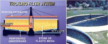
A trickling filter consists of a bed of highly permeable media on whose surface a mixed population of microorganisms is developed as a slime layer. The word “filter” in this case is not correctly used for there is no straining or filtering action involved. Passage of wastewater through the filter causes the development of a gelatinous coating of bacteria, protozoa and other organisms on the media. With time, the thickness of the slime layer increases preventing oxygen from penetrating the full depth of the slime layer. In the absence of oxygen, anaerobic decomposition becomes active near the surface of the media. The continual increase in the thickness of the slime layer, the production of anaerobic end products next to the media surface, and the maintenance of a hydraulic load to the filter, eventually causes sloughing of the slime layer to start to form. This cycle is continuously repeated throughout the operation of a trickling filter. For economy and to prevent clogging of the distribution nozzles, trickling filters should be preceded by primary sedimentation tanks equipped with scum collecting devices.
Primary treatment ahead of trickling filters makes available the full capacity of the trickling filter for use in the conversion of non-settleable, colloidal and dissolved solids to living microscopic organisms and stable organic matter temporarily attached to the filter medium and to inorganic matter temporarily attached to the filter medium and to inorganic matter carried off with the effluent. The attached material intermittently sloughs off and is carried away in the filter effluent. For this reason, trickling filters should be followed by secondary sedimentation tanks to remove these sloughed solids and to produce a relatively clear effluent.
Construction and Design
The primary factors that must be considered in the design of trickling filters include: (1) the type of filter media to be used, (2) the type and dosing characteristics of the distribution system, and (3) the configuration of the underdrain system.
1. Filter Media: The ideal filter medium is a material that has a high surface area per unit volume, is low in cost, has a high durability, and does not readily clog. The choice of filter media is more often governed by the material locally available which may include field stone, gravel, broken stone, blast furnace slag and antracite stones. Stones less than one inch in diameter do not provide sufficient pore space and may therefore result in plugging of the media and ponding. The tendency is to use larger sizes with 2 1/2 inches in diameter now considered the minimum size. Large diameter stones tend to avoid ponding situations but also limit the surface area per unit volume available for the slime layer to grow. An upper size limit of about 4 inches is therefore recommended.
2. Distribution System: The rotary distributor has become standard for the trickling filter process because of its reliability and ease of maintenance. The rotary distributor consists of a hollow vertical center column carrying two or more radial pipes or arms, each of which contains a number of nozzles or orifices for discharging the wastewater onto the bed. All of these nozzles point in the same direction at right angles to the arms and the reaction of the discharge through them causes the arms to revolve. The necessary reaction is furnished by a head of 18″ to 24″. The speed of revolution will vary with the flow rate, but it should be in the range of one revolution in 10 minutes or less for a two-arm distributor. A dosing tanks and siphon should be provided for standard rate trickling filters to shut off the flow when the head falls below that necessary to revolve the arms at the required speed. In some cases positive drive mechanisms are being used.
A clearance of 6 to 9 inches should be allowed between the bottom of the distributor arm and top of the bed. This will permit the waste streams from the nozzles to spread out and cover the bed uniformly, and it will also prevent ice accumulation from interfering with the distributor motion during freezing weather.
Fixed spray nozzles were used when trickling filters were first developed. The nozzles were attached to pipes laid in the filter medium and were fed intermittently from a siphon controlled dosing tank. By this method, wastewater is applied to the filter for short periods of time. Between applications the filter has rest periods while the dosing tank is filling. Many types and shapes of nozzles were developed and the siphon dosing tank was designed to attain the best possible even distribution of wastewater over the entire surface of the filter. At best, the distribution was not even and there were areas of the filter on which very little wastewater was sprayed.
In addition, due to the greater number of nozzles used for the distribution of the wastes, clogging and increased operational and maintenance problems were encountered.
1. Underdrain System: The underdrain system in trickling filters serves two purposes: (a) to carry the wastewater passing through the filter and the sloughed solids from the filter to the final clarification process, and (b) to provide for ventilation of the filter to maintain aerobic conditions. The underdrains are specially designed vitrified clay blocks with slotted tops that admit the wastewater and yet support the media. The blocks are laid directly on the filter floor, which is sloped toward the collection channel at a 1 to 2 percent gradient. Since the underdrains also provide ventilation for the filter it is desirable that the ventilation openings total at least 20% of the total floor area. Normal ventilation occurs through convection currents caused by a temperature differential between the wastewater and the ambient air temperature. In deep filters or heavily loaded filters, there may be some advantage in force ventilation.
Filter Classification
Trickling filters are classified by hydraulic or organic loading, as high-rate or low-rate.
The organic load on a filter is the BOD content in pounds applied to the filter. This is usually expressed as pounds of BOD per day per 1000 cubic feet of filter medium or pounds of BOD per day per acre foot. The hydraulic load, including recirculation flow if used, is the gallons of flow per acre of filter surface per day.
Low-rate filters are relatively simple treatment units that normally produce a consistent effluent quality even with varying influent strength. Depending upon the dosing system, wastewater is applied intermittently with rest periods which generally do not exceed five minutes at the designed rate of waste flow. With proper loadings the low-rate trickling filter, including primary and secondary sedimentation units, should remove from 80 to 85 percent of the applied BOD. While there is some unloading or sloughing of solids at all times, the major unloadings usually occur several times a year for comparatively short periods of time.
High-rate filters are usually characterized by higher hydraulic and organic loadings than low-rate filters. The higher BOD loading is accomplished by applying a larger volume of waste per acre of surface area of the filter.
One method of increasing the efficiency of a trickling filter is to incorporate recirculation. Recirculation is a process by which the filter effluent is returned to and reapplied onto the filter. This recycling of the effluent increases the contact time of the waste with the microorganisms and also helps to “seed” the lower portion of the filter with active organisms.
When recirculation is used, the hydraulic loading per unit area of filter media is increased. As a result, higher flow velocities will usually occur causing a more continuous and uniform sloughing of excess growths. Recirculation also helps to minimize problems with ponding and restriction of ventilation.
Recirculation can be continuous or intermittent. Return pumping rates can either be constant or variable. Sometimes recycling can be practiced during periods of low flow to keep the distributors in motion, to prevent the drying of the filter growths, and to prevent freezing during colder temperatures. Also, recirculation in proportion to flow may be utilized to reduce the organic strength of the incoming wastes, and to smooth out diurnal flow variations.
Recirculation can be accomplished by various techniques. Some of which are as follows:
Biofilter: The bio-filter is a high-rate filter, usually 3 to 4 feet in depth, employing recirculation at all times. The recirculation in this case involves bringing the effluent of the filter or of the secondary sedimentation tank back through the primary settling tank. The secondary settling tank sludge is usually very light and can be continually fed back to the primary settling tank where the two types of sludges are collected together and pumped to the digester.
Accelo-Filter: The accelo-filter includes recirculation of unsettled effluent from the filter back to the inlet of the filter distributor. It is used for both low-rate and high-rate filters, the former being applicable if a well nitrified effluent is required.
Aero Filter: The aero-filter is still another process which distributes the wastewater by maintaining a continuous rain-like application of the wastewater over the filter bed. For small beds, distribution is accomplished by a disc distributor revolving at a high speed of 260 to 369 rpm set 20″ above the surface of the filter to give a continuous rain-like distribution over the entire bed. For large beds a large number of revolving distributor arms, 10 or more, tend to give more uniform distribution. These filters are always operated at a rate in excess of 10 million gallons per acre of surface area per day.
High-rate trickling filters, including primary and secondary sedimentation, should, under normal operation, remove from 65 to 85 percent of the BOD of the wastewater. Recirculation should be adequate to provide continuous dosage at a rate equal to or in excess of 10 million gallons per acre per day. As a result of continuous dosing at such high rates, some of the solids accumulated on the filter medium are washed off and carried away with the effluent continuously.
High-rate trickling filters have been used advantageously for pretreatment of industrial wastes and unusually strong wastewaters. When so used they are called “roughing filters”. With these filters the BOD loading is usually in excess of 110 pounds of BOD per 1000 cubic feet of filter medium.
Generally, most organic wastes can be successfully treated by trickling filtration. Normally food processing, textile, fermentation and some pharmaceutical process wastes are amenable to trickling filtration.
Some industrial wastewaters which cannot be treated by trickling filtration are those which contain excessive concentration of toxic materials, such as pesticide residues, heavy metals, and high acidic and alkaline wastes.
Since the organisms growing on the media are temperature dependent, climatic changes will affect the filter’s performance. The organisms metabolic rate increases with increasing temperature and warmer weather. Therefore, higher loadings and greater efficiencies are possible in warmer temperatures and climates, if aerobic conditions can be maintained in the filter.
Common Problems
Due to its simple design, in actual operation the trickling filter is one of the most trouble-free types of secondary treatment processes. It requires much less operating attention and process control than the activated sludge system, but some problems do exist. The following is a summary of some of the more common problems and cures:
1. Ponding is normally the result of: (a) excessive organic loading without a corresponding higher recirculation rate, (b) use of media which is too small, (c) clogging of underdrain system, (d) non-uniform media size or breaking up of media, and (e) trash or debris in filter voids.
Ponding can cause odors and decrease filter efficiency.
Minor Ponding can be eliminated by:
1. Spraying the surface with high pressure water hose.
2. Stirring or agitating ponding area with stick, rake, etc.
3. Dousing the filter with chlorine. Applying chlorine to a ponding filter by chlorinating at the dosing tank to produce a residual of about one to two mg/L at the nozzles may help reduce ponding. Chlorination is continued until the filters are free. There may be some deterioration of efficiency of the filters during chlorination. Obviously, if ponding is caused by the size of the media, chlorination will be of no benefit. If the ponding is caused by overloading, chlorination may be of temporary benefit. If ponding was caused by excessive growths, this deteriorating condition will usually not return until conditions, such as temperature, that caused the excessive growth are repeated.
4. Flooding filter and keeping the media submerged for approximately 24 hours will sometimes cause the growth to slough. Growths become anaerobic and tend to release from media.
5. Shutting off the flow to the filter. The growths will die and tend to be flushed out when the unit is put back into service.
Odors. Since the trickling filter is an aerobic process, no serious odors should exist. If foul odors are present, anaerobic conditions are the most likely cause. Anaerobic conditions usually predominate next to the media surface.
If the surface of the slime growth is aerobic, odors should be minimal. If odors are present, corrective action should be taken immediately or the condition could get worse. Some corrective measures are:
2. Try to maintain aerobic condition in the collection system and in the primary treatment units.
3. Check the ventilation of the filter for clogging and stoppages.
4. Check the underdrain system for clogging and stoppages.
5. Increase recirculation rate; this usually provides added oxygen to the filter and may increase sloughing.
6. Keep wastewater in filter; do not allow it to splash on exposed surfaces, weeds, or grass.
7. Add odor-masking agents.
8. Pre-chlorination at primary tank influent or at the dosing tank. The dose used is not sufficient to produce residual chlorine but only to destroy the odors. Chlorination to a residual of less than 0.5 mg/L normally does not interfere with the activity of the living organisms and thus does not affect the purification obtained by the operation of a trickling filter. However, chlorination of a trickling filter influent cannot be used until after the filter has been in active operation. Except in a large plant, the chlorine dose is generally set at about half the chlorine demand and not adjusted for moderate variations in flow or strength.
9. Induce unloading of a trickling filter. A shock dose of chlorine that will produce a residual of about 10 mg/L in the filter influent may be applied. It requires a fairly large dose of chlorine to produce this amount of residual. As it is only to be maintained for a short period of time, it is most economical to apply during the night when the flow is low and the chlorine demand at a minimum. The chlorine is applied at the dosing tank, generally by making a slurry of liquid hypochlorites and pouring it into the dosing tank. Two dosing discharges containing 10 mg/L residual are generally enough to cause the filter to unload the next day. A word of caution — when a filter is made to unload it does so quickly if at all and a very large volume of secondary sludge is produced in one or two day. Addition of this large quantity of sludge to the digesters has caused foaming on occasions.
It should be noted that sometimes during hot weather odors will be noticeable even from a filter in good operating condition. This problem can be eliminated by the use of masking agents.
Filter Flies are a nuisance to plant personnel and nearby neighbors. These tiny, gnat-size flies are called psychoda. They are occasionally found in great numbers, preferring an alternate wet and dry environment for development.
The flies are most frequently found in low or standard rate filters with an intermittent dosing system.
Control can be accomplished by:
Increasing recirculation. A continuous waste flow to the filter will tend to wash fly larvae from the filter.
Flushing the side walls of the filter by opening the flap valve at the end of the distributor arm.
Flooding the filter intermittently to prevent completion of the fly life cycle. This life cycle can be as short as seven days in warm weather. Filters should be flooded for approximately 24 hours.
The addition of chlorine, which is toxic to the flies and larvae.
Keeping the plant grounds neat, clean and free from excessive weeds, plants, and grass, which are excellent breeding grounds for the flies.
Weather Problems. Cold weather can cause an occasional build-up of ice on the media, walls, distributor arms and orifices, resulting in operating problems and loss of efficiency. During cold temperatures, the organism’s metabolic process slow down and as a result efficiency decreases.
Measures which can be implemented to reduce cold weather problems are:
Decrease the recirculation rate to prevent splashing at distributor arm, but maintain sufficient flow to keep the filter working.
Adjust orifices at splash plates to reduce the spraying effect.
Construct wind screens or covers to reduce heat loss.
Break up any ice build-up.
Partially open flap gates at end of distributor arm to allow for a stream of water rather than a spray of water.
Warm weather creates its own unique problem areas as previously discussed.
Ponding resulting from sloughings due to excessive organism growth.
Odors resulting from anaerobic conditions. The dissolved oxygen demand is higher in warmer weather due to higher organism activity.
Filter Flies
Degradation of final effluent due to excessive loading from sloughings on final sedimentation tanks.
Trickling Filter Systems Design & Application
The Modern
Trickling Filter
The modern trickling filter is quite advanced from the rock filters of old. These new filters are engineered systems that provide a very cost-effective process for treatment of both domestic and industrial wastewater. Trickling filters are routinely designed to treat wastewater to NPDES standards including ammonia removal and/or they can be designed to provide low-cost roughing of high-strength wastewater. Trickling filters are often teamed up with activated sludge systems to reduce the overall cost of wastewater treatment
PVC Trickling Filter Media
The introduction of thermoformed PVC sheetmedia is largely responsible for the success of the modern trickling filter. This advancement allows construction of modules of superior compressive strength and higher void-volumes necessary for stacking to heights not achievable with rock filters. In addition, greater specific surface area makes higher organic loadings possible and makes more efficient nitrification towers possible. Deeper bio-towers are easily ventilated because of the higher void volumes.
New Trickling Filter Installations
New trickling filter installations take advantage of the benefits offered by PVC sheet media:
Low Power Requirements
Trickling filters only require power for pumping and do not need large power-hungry aeration blowers like suspended growth systems such as Activated Sludge and Sequencing Batch Reactors. For this reason, the trickling filter is frequently used as a roughing process in tandem with activated sludge systems
Simple Operation
The operational requirements of trickling filters are less demanding than those of activated sludge systems. However, there is enough flexibility to allow the operator to optimize performance. For example, recycle rates, flushing rates, and wetting rates are important variables that can be adjusted to accommodate changing organic and hydraulic loadings. Far less control data must be acquired andmonitored for tricklingfilter operation than for an activated-sludge system or sequencing-batch system.
Lower Sludge Production
Trickling filters produce less sludge than suspended-growth systems. The sludge that is produced tends to settle well because it is compact and heavy.
The Elements of the Modern Trickling Filter
• High Specific Surface Area
• Wide Flow Passages
• Superior Ventilation (Open Plenum and High Void Volume)
• Heights up to 30 feet
Upgrading Rock Filters with Sheet Media
Old rock trickling filters are being upgraded and rehabilitated with plastic sheet media. The greater surface area and higher void volume of structured-sheet media provides improved treatment efficiency, even at the very shallow depths used in old rock filters (typically 3 ft. to 7ft.). In some cases, the walls of the filter beds may be extended upward a few feet for additional increases in the rated capacity of the retrofitted plant.
Compared with rock, plastic sheet media has 2-3 times the specific surface area, which provides proportionally more area for biomass attachment. Also, the increase in the void volume from 50% to 95% improves the airflow and hydraulic loading capacity, decreases the tendency of the system to clog with biomass, and reduces odors associated with anaerobic pockets caused by silting.
Components of Trickling Filter Towers The components shown are common to most trickling filters, regardless of the type (shallow rock retrofit, deep BOD roughing tower, or nitrification tower).
Structured-Sheet Plastic Media
Structured-sheet plastic media is the heart of the trickling filter. The specific type of media to be used in a given system is based on the organic loading and wastewater treatment objectives: roughing, complete treatment, or nitrification. The media’s specific surface area, void volume, and distribution characteristics are important to the specific application and system performance.
The wetting rate, organic load, ammonia load, temperature of the wastewater, and desired effluent quality determine the volume of media required.
A typical media installation layout consists of modules 2 ft. wide x 2 ft. high x 4 ft. or 6 ft. long placed in layers, each layer placed at a right angle to the layer below. The media is cut to fill the tank at the periphery.
Media Support System
In newer towers, the media is supported well above the concrete floor of the filter tower. This creates a plenum that allows air to move freely through the vent windows and under the media/lintel structure. The air moves up through the tower in summer (when the air is warmer than the wastewater) or down through the tower in winter (when the air is colder than the wastewater), providing oxygen to the bacteria throughout the tower.
Domes & Forced-Draft Ventilation
Domes and forced-draft ventilation systems are often used in new trickling filter systems. Older, open systems relied strictly on natural draft for ventilation. The dome at the top of the trickling filter serves to reduce temperature losses in the winter and shield the system from strong winds that could interfere with ventilation. In some systems, the dome is also used to collect trickling filter vent gasses that are then channeled to scrubbers.
Rotating-Arm Distributor
A rotating arm distributes the mixed wastewater/recycled water over the top of the media. The distribution arm can be driven by hydraulic reaction or by mechanical means. Typically, the speed of rotation can be adjusted to effect higher media flushing intensity. Speed change in the distributor mechanism is particularly valuable in systems that have high organic loads. In nitrification towers, speed change is used to flush predators, such as snails, from the tower.
Recycle Pump
A collection trough at the bottom of the tower collects the treated wastewater and channels it to a sump, where it can be recycled as wastewater or discharged to a secondary clarifier.
Types of Trickling Filter Media
Cross Flow Media
Cross flow media is made of sheets formed with alternating corrugations at 60° to vertical. The sheets are solvent-welded to each other to form modules for easy stacking in the biofilter vessel. The down-flowing liquid is split at each cross point creating 180 redistribution points per foot of depth for Brentwood CFS-3000 (31 ft2/ft3) media and up to 720 mixing points per foot of depth for the CF-1900 (48 ft2/ft3).
CF-1900
Vertical Flow Media
Vertical flow media has vertical channels with contact points at one foot intervals. Lacking the cross-mixing points of cross flow media, vertical flow media redistributes the flow only at module interface. As a result, vertical flow media has superior bio-solids flushing action.
VF-5000
Mixed Media
The optimal configuration of media in the modern bio-tower over 16 ft. deep is the combination of cross flow media in the upper two layers with vertical media in the lower layers. This configuration combines the superior distribution properties of cross flow media with the reduced potential for clogging of vertical flow media, to give consistent and efficient biological wastewater treatment.
Trickling Filter Applications
BOD Roughing and Secondary Treatment
For pre-treatment of high-strength wastes or BOD reduction prior to further treatment for nitrification, CFS-3000 alone (for shallow rock filter retrofits) or CFS-3000 in combination with VF-5000 (30 ft2/ft3) in deep bio-towers are the usual selections because of the large non-clogging passages, maximum re-distribution points, and good ventilation.
Nitrification
Bio-towers intended for ammonia oxidation following BOD roughing can use higher surface area media with smaller passages, such as the CF-1900 (48 ft2/ft3) alone or in combination with VF-3800 (40 ft2/ft3) media. Thinner bio-films in the nitrification process are less likely to cause plugging of the narrow passages.
Other Applications for Structured Media
While not normally considered trickling filters, two other types of biological waste treatment processes commonly use structured-sheet media. Commonly referred to as “submerged fixed film,” anaerobic decomposition of wastewater is achieved in covered tanks filled with media to support the attached growth anaerobic organisms. Nitrogen removal via biological de-nitrification is accomplished by mixing nitrified wastewater with a carbon source, such as raw wastewater, and passing that liquid through media-filled tanks containing denitrifying organisms.
Trickling Filter Characteristics
Click here for a performance comparison between Rock Filters and PVC Media Filters. Table will open in a separate window. Trickling Filter Process Design The first process design approach to use fundamental principles was published by Velz(1) in 1948. His equation expressed BOD removal as a first order function of filter depth:
Schultz modified the Velz equation to account for hydraulic loading rate (gal/min/ft2), and Germain later applied Schultz’s formula to plastic trickling filter media.
MOP 8 provides a large array of measured values for the coefficients in Germain’s formula for a variety of wastewater types. The effect of temperature is generally given as:
Process Design Assistace from Brentwood
Brentwood can provide design assistance using a proprietary model based on bio-filter performance data compiled from a number of sources, including both published and non-published data.
Wetting Rates
The overall application rate of wastewater to the trickling filter, including recirculation, expressed as gpm/ft2 of the filter area, is known as the “Wetting Rate.” The desired wetting rate ranges from 0.05 gpm/ft2 to a maximum of 3 gpm/ft2, but is more typically in the range of 0.25 to 1 for BOD removal systems and 0.75 to 2 gpm/ft2 for
nitrification trickling filters.
If the average wetting rate is too low, the water may not penetrate the depth of the filter bed uniformly. It may channel away from some areas and leave damp unwetted areas that can act as incubators for pests like filter flies and snails (in nitrification towers). Also, biological populations not continuously wetted and fed by wastewater become ineffective. Those areas of the filter tower will not be available to provide effective treatment of wastewater during periods of higher flow. Semi-dry biomass can also putrefy and create odor problems.
Recycle of treated wastewater is an effective method of keeping all areas and depths of the trickling filter biologically active when the influent flow is too low for proper wetting.
Instantaneous Wetting Rate
From the work of the German wastewater treatment industry, a term has been developed that identifies the Instantaneous Application Rate. This term is the SpülKraft Rate, or SK Rate, that has the units of mm of water per pass of the distributor arms.
Hydraulically-driven rotary distributors in the normal operating mode usually rotate at a rate of 1 revolution per 3/4 to 1-1/2 minutes and have two or four arms. The SK Rate may be in the range of 0.3 to 0.5 mm per pass in rock filters and from 5 to 30 mm per pass in more modern filters.
If recycle capacity is minimal and the operator has the ability to slow the rotation speed of the distributor, it is possible to compensate somewhat for low wetting rates by using higher SK values. Higher SK values will provide more complete penetration of the filter media depth and keep the bulk of the filter wetted.
Short cycle times of dryness between flushing will not be as detrimental to the biomass as a general starvation for water in pockets of media that are by-passed at low wetting rates.
Recirculation Benefits
Recirculating treated effluent to the trickling filter dilutes the influent wastewater entering the trickling filter. Since the BOD removal process is first order (i.e., the rate of removal of BOD is affected by the initial concentration of BOD), recirculation helps distribute the loading evenly through the depth of the filter. It also helps to manage the diurnal variation in loading while maintaining a minimum wetting rate throughout the day. In general, higher recirculation ratios (recirculation flow rate : influent flow rate) the better the effluent quality, at least to the point where the hydraulic retention time in the filter bed becomes too short. Typical recirculation rates are 1-3 times the daily average influent wastewater flow.
When dealing with nitrification filters, the benefit of recirculation only applies to maintaining high wetting rates, since the rate of ammonia removal is zero order to ammonia concentrations down to 2 ppm NH3-N concentrations. This means that only the availability and mass of the bacteria on the tower determine ammonia removal as long as the ammonia is greater than 2 ppm. Media Support Systems
In a typical arrangement, the bottom layer of media modules are placed on 8 or 10-inch wide support beams spaced across the tank on 2 ft. centers. In the case of 10 inch support beams, a 2 inch wide center channel provides proper drainage. At the tank wall and around the center distributor column, a ledge 4 incheswide is used to support small pieces of cut media
AccuPier Support System
An alternative to the conventional concrete beam & pier system is the Brentwood AccuPier® System. This pre-engineered support system, consisting of field-adjustable plastic stanchions and fiberglass grating, is more economical and offers better air flow than concrete beam & pier supports. The open structure of the AccuPier system provides excellent ventilation and drainage. The glass-reinforced ABS piers have field-adjustable bases to accommodate sloping floors. The PVC pier stanchions are cut to length for the specific installation. Fiberglass grating in nominal 12 inch widths x 20 ft. lengths, pre-cut for the tank dimensions, spans the piers to give a flat, level surface to support the media. The piers are arranged in rows 2 or 3 ft. apart, and the spacing between piers within the row varies from 2 to 4 ft, depending on tower height and grating strength. Media Strength
Dedicated Bond Joints
Because the modules are constructed of vertical, corrugated sheets of PVC, the structural strength of the modules is dependent on the bonds between adjacent panels. Solvent welding at dedicated bond points, formed in the sheets to provide adequate bonding surface, ensures the structural integrity of AccuPac media
Compressive Strength of Modules
The structural integrity of the media is paramount to the longevity of the filter. Typically, each layer of the media is constructed to support the static weight of the media above, including the attached biomass and the transient loading of the applied wastewater. Industry practice is to use a factor of 40 lb/ft2 per foot of tower height. The bottom layer is constructed to a minimum standard of 1000 lb/ft2 to support the full height of the tower on the support beams. The top layer is also designed to support 1000 lb/ft2 to accommodate possible foot traffic during maintenance. This can be reduced to 700 lbs/ft2 when protective surface grating is used. Module Testing
In addition to the physical and mechanical properties of the PVC sheet stock used in forming the media sheets, the structural strength of the modules is also determined by material sheet thickness and module configuration. For example, because the CF-1900 has more sheets per 24 inch wide module than the CFS-3000, it has greater surface area, and is, therefore, inherently stronger than a CFS-3000 module with the same sheet thickness. Crossflow modules are inherently stronger than vertical flow modules because of the crossed alignment of the bond joints. Therefore, empirical testing is necessary to ensure structural soundness of the wide variety of media types and sheet thicknesses of the PVC material. An industry-standard test procedure uses four modules in two layers placed at right angles to each other in a hydraulic test apparatus. The module deflection is measured as a function of the load applied. The deflection should not exceed 1.5% at the design load. Media Protection
The hydraulic impact of the wastewater and braking jets of the hydraulic distributor can, over time, damage the surface of the media. Also, it is often necessary to walk on the surface of a trickling filter. Good tower hygiene requires removal of debris that accumulates on the top of the filters. The distributor arms and bearings in the distribution tower also need to be serviced regularly to maintain proper operation and equipment longevity.
Brentwood AccuGrid
Brentwood AccuGrid™ polypropylene grating provides that additional protection for the surface of the filter surface. This grid, when placed over the top surface of the media in the trickling filter system, will provide a non-skid walking surface that is strong and durable against foot traffic and will help to reduce the hydraulic impact on the media.
Economic Considerations
While direct economic comparison to other treatment processes can only be made on a case-by-case basis, some general comparisons can be made.
• The containment vessel for bio-towers does not need to be constructed to hold the weight of the wastewater, as do activated sludge tanks. Vessels are often built of low-cost, pre-cast concrete panels or bolted steel plates.
• Power consumption for bio-towers is limited to pumping wastewater and re-circulated wastewater. No aeration power is needed (with the exception, in certain cases, of ventilation fans.)
• Maintenance for bio-towers is limited to the distributor arm and pumps. Blowers, air diffusers, return sludge pumps, and associated electrical equipment and controls are not needed.
• Less operator labor is needed to monitor, sample, and make adjustments to the process for the simpler trickling filter.
• Odor containment, if desired, is accomplished with the simple addition of a dome cover to the bio-tower tank.
The Brentwood Trickling Filter System A complete system for the internal components of a typical trickling filter includes: media support system; structured sheet media; and protective surface grating. As a manufacturer of all these components, Brentwood Industries is capable of supplying a complete system, with a full structural warranty. All components are engineered by Brentwood to work with each other and provide the lowest installed cost. In addition to engineering the system and manufacturing the components, Brentwood can provide on-site assistance for installation of the system.