CHAPTER VI
STRUCTURAL DESIGN OF TYPE-IIBUILDING
Introduction:
In this chapter, the four storied building is analyzed and designed by ultimate strength design (USD) method as per discussions made in Chapter III and references provided by Winter and Nilson (1997 & 2003). For space limitations, one set of design example is presented here in detail from each component of the building such as slab, floor beam, column, grade beam and footing. The cross-sectional dimensions along with reinforcement arrangement of the rest are shown in a tabular form. Finally full design of the stair case has been provided.
Analysis and design of building components
Design of slab:
All slab panels are analyzed and designed by following the ‘ACI Moment Coefficient procedure’ (Appendix I). Typical floor plan and panel plan are given in Appendix VII and Appendix VIX respectively. Analysis and design of panel groups (S-1~S-3) are presented below.
Design data
Design procedure – ACI moment Co-efficient
Materials:
= 40 ksi
= 3 ksi
= 150 pcf
= 120 pcf
Loadings:
F.F + Partition wall = 30 psf
L.L = 40 psf
Slab Panel S -1
Panel size = 28′-2″×20′-6″
Beam width = 12″
Clear span size =27′-2″×19′-0″
Panel ratio,
Panel type = Two-way slab (Case – 4)
1) Load calculation:
Slab thickness
Self weight of slab
Floor finish +P-wall = 30 psf.
Live load = 40 psf.
Factored load = 1.2 WDL + 1.6 WLL
= 1.20 × (81.25+30) +1.6×40
= 197.5 psf
ll) Moment calculation:
Support moment:
Mid span moment:
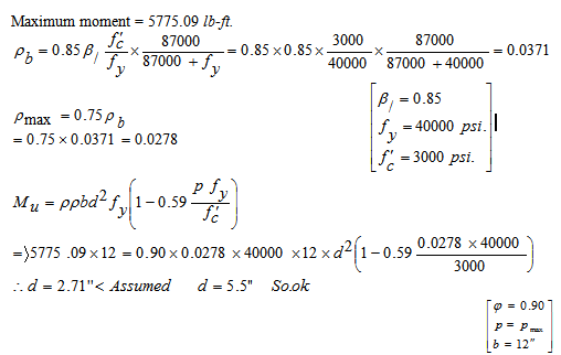
lll) Check for d :
Maximum moment = 5775.09 lb-ft.
lV) Reinforcement calculation:
A. Short direction steel
Steel for positive moment at mid span
< 200 psi
Use # 3 bar which area = 0.11
Spacing
Use # 3 @ alternate cranked bars.
Alternative bars should be cranked both at continuous and discontinuous edges.
Steel for negative moment at both supports
So provided 1# 3 bar extra top between two ckd. bars.
B. Long direction steel
Steel for positive moment at mid span
(+)ve MB = 1745.49 lb – ft
Spacing
Use # 3 @ alternate cranked bars.
Alternative bars should be cranked both at continuous and discontinuous edges.
Steel for negative moment at both supports
(-)ve MB = 2770.12 lb – ft
So provide 1-# 3 bar extra top between two ckd. bars.
Slab Panel S-2
Panel size = 7′-0″×5′-8″
Beam width = 12″
Clear span size = 6′-0″×4′-8″
Panel ratio,
Panel type = Two-way slab (Case – 2)
1) Load calculation:
Slab thickness
Self weight of slab
Floor finish +P-wall = 30 psf.
Live load = 40 psf.
Factored load = 1.2 WDL + 1.6 WLL
= 1.20× (62.50+30) +1.6×40
= 175 psf
ll) Moment calculation:
Support moment:
Mid span moment:
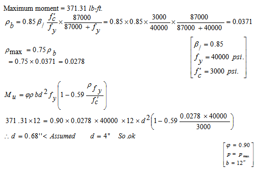
lll) Check for d:
Maximum moment = 371.31 lb-ft.
lV) Reinforcement calculation:
A. Short direction steel
Steel for positive moment at mid span
Use # 3 bar which area = 0.11
Spacing
Use # 3 @ alternate cranked bars.
Alternative bars should be cranked both at continuous and discontinuous edges.
Steel for negative moment at both supports
So provided 1 # 3 bar extra top in between two ckd. bars.
B. Long direction steel
Steel for positive moment at mid span
(+)ve MB = 105.02 lb – ft
Spacing
Use # 3 @ alternate cranked bars.
Steel for negative moment at both supports
-MB = 214.37 lb – ft
Crank to crank spacing
So provide 1-# 3 extra top between two ckd. bars.
Slab Panel S -3
I) Check for one-way slab
Panel size = 7′-0″×15′-6″
Beam width = 12″
Length, L=15′-0″ and width, w =7′-0″
Panel ratio,
So the slab will be designed as one-way slab.
II) Calculation of slab thickness:
Minimum slab thickness
Thickness correction for
Corrected thickness, h = 3″×0.80 =2.40″
Slab thickness let, h =4″
Effective depth, d = 4 -1=3″
III) Moment calculation:
L L= 40 psf
Factored load =1.2×DL+1.6×LL = 1.2×80+1.6×40 =160 psf = 0.16 ksf
(+)ve moment at mid span
(-)ve moment at interior support
lV) Check for d:
Maximum design moment= 0.784 k-ft
V) Reinforcement calculation
A. Temperature & shrinkage steel.
Use # 3 bar as Temperature steel.
Use # 3 bar @ 13.50” c/c.
B. Main bar
(-)ve Moment at Interior support = 0.784 k-ft
(-)ve As for Int. support = ρbd = 0.0023×12×3=0.083 in2/ft
(+)ve Moment at mid span = 0.56 k-ft.
We provided # 3 as main steel
Spacing at mid span =
So spacing at mid span =
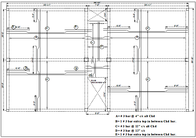
A detail of slab reinforcement arrangement of all panels (S-1 ~ S-3) is given in Table 6.1 and Figure 6.1.
Bar arrangement, cut-off and bent up, bar spacing etc. are done as per discussions and ACI/BNBC Codes provisions presented in Chapter III.
Table 6.1: Details of slab reinforcement arrangement of all Panels (S-1~S-3)
| Panel | Length (feet) | Moment (pound-feet) | Area of steel inch (sq.)/ft | Spacing (inch c/c) | ||||||||||
LA | LB | Negative | Positive | Negative | Positive | Negative (Extra top in between crank) | Positive (Main bar) | |||||||
LA | LB | LA | LB | LA | LB | LA | LB | LA | LB | LA | LB | |||
S-1 | 19 | 27.17 | 5775.09 | 2770.12 | 3279.68 | 1745.49 | 0.343 | 0.33 | 0.33 | 0.30 | #3-1 | #3-1 | #3 @ 4″ | #3 @4″ |
S-2 | 6 | 14.91 | 784 | —– | 560 | —– | 0.083 | 0.062 | 0.072 | #3-1 | —– | #3 @ 12″ | #3 @12″ | |
S-3 | 5.67 | 6 | 371.31 | 214.37 | 183.28 | 105.02 | 0.24 | 0.21 | 0.10 | 0.21 | #3 -1 | #3-1 | #3 @ 5.5″ | #3 @ 5.5″ |
LA – Short direction
LB – Long direction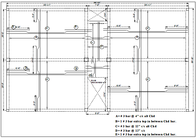
Design of floor beam:
All floor beams are analyzed and designed by following the ‘ACI Moment Coefficient procedure’ (Appendices I & XVI). Typical lay-out plan of all floor beams is given in Appendix-XI. Analysis and design of all beam groups (F. B – 1~F.B-6) are presented below.
Design data
Design procedure = ACI moment Co-efficient
Materials:
= 60 ksi
= 3 ksi
= 150 pcf
= 120 pcf
Main wall thickness = 5″
Floor beam F.B-1
Let depth of beam =25″
Beam size =12″×25″
l) Load calculation:
Self weight of beam =
Main wall / Partition wall weight
Load coming from slabs
S-1 DL =111.25× 19′×0.5×0.81×2= 1712.13 lb / ft
Total dead load, DL = 312.50+396+1712.13=2420.63 lb/ft
Live load, LL = 40×19′-0″×0.5×0.81×2 = 615.60 lb / ft
Factored load = 1.2DL+1.6LL = 1.2×2420.63+1.6×615.60 =3889.72 lb/ft
=3.89 k / ft
ll) Moment calculation & d check:
(-) ve moment at Ext. support =
(+) ve moment at mid span =
(-) ve moment at Int. support =
T-beam check
For interior beam
center to center distance of the beam =20′-0″ =240″
will be the smallest of the above, = 81.5″
Let, a = slab thickness = 6.5″
And assume it is a singly beam.
So it is not a T-beam.
Considering double layers of steel, effective depth of the beam, d= 25″-4″= 21″
Check for‘d’
Maximum Moment = 287.16 k-ft
lll) Reinforcement calculation:
(+)ve steel at mid span
(- )ve Steel at exterior support
(- )ve Steel at Interior support
IV) Stirrup design:
Shear at 1st Interior support,
Critical shear at d distance,
Concrete shear strength,
Allowable strength,
Since, < , So stirrup is required.
Shear carried by stirrup =71.85-20.71=51.14 k
Floor beam F.B-2
Let, beam width =12″
Depth of beam=
Take beam size = 12″×20″
l) Load calculation:
Self weight of beam F.B-2 =
All main wall weight
Load coming from slab, S-1 = 111.25×19′-0″×0.81/2 = 856.06 lb / ft
Total dead load, DL = 250+416.5+856.06 = 1522.56 lb / ft
Live load from slab, S-1 = 40×19′-0″x0.81/2 = 307.80 lb / ft
Total factored load = 1.2DL+1.6LL
= 1.2×1522.56+1.6×307.80 = 2319.55 lb-ft =2.32 k / ft
ll) Moment calculation:
(-)ve moment at Ext. support = =
(+)ve moment at mid span = =
(-)ve moment at Int. support = =
III) T-beam& d check:
T-beam check
Center to center beam distance=12+0.5×(19′-0″)×12=126″
will be the smallest of the above, =39.17″
Let, a= slab thickness = 6.5″ and assume it is a singly beam
So it is not a T-beam, and it will be designed as a singly beam
Effective depth of the beam, d =20-4 =16″ (considering double layer of steel)
Check for d
Maximum moment, =171.33 k-ft
lV) Reinforcement calculation:
(+)ve steel at mid span
(-)veSteel at Interior support
(-)ve Steel at exterior support
V) Stirrup design:
Shear at 1st Interior support,
Critical shear at ′d′ distance,
Concrete shear stress,
Allowable stress,
Since, < , so stirrup is required.
Shear carried by stirrup =28.32-17.25=11.07 k
Floor beam F.B-3
Let, beam width = 12″
Depth of beam =15″
Size of beam =12″×15″
l) Load calculation:
Self weight of beam F.B-3 =
All main wall weight
Load coming from slab, S-1 = 111.25×27′-2″×0.19/2 = 287.15 lb / ft
Total dead load, DL = 187.50+437.50+287.15 = 912.15 lb / ft
Live load from slab, S-1 = 40×27′-2″×0.19/2 = 103.25 lb / ft
Total factored load = 1.2DL+1.6LL
= 1.2×912.15+1.6×103.25= 1259.76 lb-ft =1.26 k / ft
ll) Moment calculation:
(-)ve moment at Ext. support = =
(+)ve moment at mid span = =
(-)ve moment at Int. support = =
III) T-beam& d check:
T-beam check
(Center to center beam distance) =12+0.5 × (27′-2″) ×12=175″
will be the smallest of the above, = 31″
Let, a = slab thickness = 6.5″
And assume it is a singly beam
So it is not a T-beam, it will be designed as a singly beam.
Now effective depth of the beam, d =15-2.5 = 12.5″ (considering one layer of steel).
Check for d
Maximum moment, =45.48 k-ft
lV) Reinforcement calculation:
(+)ve steel at mid span
(-)ve Steel at Interior support
(-)ve Steel at exterior support
V) Stirrup design:
Shear at 1st Interior support,
Critical shear at ′d′ distance,
Concrete shear stress,
Allowable stress,
Since, < , so stirrup is required.
Shear carried by stirrup = 16.60-12.32 = 4.28 k
Floor beam F.B-4
Let, beam width = 12″
Depth of beam = 15″
Size of beam = 12″×15″
l) Load calculation:
Self weight of beam F.B-4 =
Self weight of 5″ wall
Load coming from slab, S-1 = 111.25×27′-2″×0.19/2 = 287.15 lb / ft
Load coming from slab, S-3 = 80×7/2 = 280 lb/ft
Total dead load, DL = 187.50+437.50+287.15+280 = 1192.15 lb / ft
Live load from slab, S-1 = 40×27′-2″x0.19/2 = 103.25 lb / ft
Live load from slab, S-3 =40×7/2=140 lb/ft
Total live load, LL = (103.25+140.00) =243.24 lb/ft
Total factored load = 1.2DL+1.6LL
= 1.2×1192.15+1.6×243.24= 1819.76 lb-ft =1.82 k / ft
ll) Moment calculation:
(-)ve moment at Ext. support = =
(+)ve moment at mid span = =
(-)ve moment at Int. support = =
Maximum moment, = 65.70 k-ft
III) T-beam& d check:
T-beam check
(Center to center beam distance)=12+0.5×(27′-2″)×12=175″
will be the smallest of the above, =31″
Let, a=slab thickness=6.5″ and assume it is a singly beam
So it is not a T-beam, and it will be designed as a singly beam
Now effective depth of the beam, d=15-2.5=12.5″ (considering one layer of steel)
Check for d
Maximum moment, =65.70 k-ft
lll) Reinforcement calculation :
(+)ve steel at mid span
(-)veSteel at Interior support
(-)veSteel at exterior support
IV) Stirrup design:
Shear at 1st Interior support,
Critical shear at d distance,
Concrete shear stress,
Allowable stress,
Since, < , So stirrup is required.
Shear carried by stirrup =23.86-12.32=11.54 k
Floor beam F.B-5
Let, beam width = 12″
Depth of beam =12″
Size of beam =12″×12″
Effective depth, d =12-2.5=9.5″
l) Load calculation:
Self weight of beam F.B-5 =
Self weight of 5″ wall
Load coming from slab, S-1 = 111.25×27′-2″×0.19/2 = 287.15 lb / ft
= (150+437.50+287.15) = 874.65 lb/ft
Live load from slab, S-1 = 40×27′-2″x0.19/2 = 103.25 lb / ft
Factored load (B to C) = 1.2DL+1.6LL
=1.2×874.65+1.6×103.24=1214.76 lb/ft
Dead load slab, S-3 = 0.55/2×92.50×6′-0″ = 152.62 lb / ft
Live load from slab, S-3 = 0.55/2×40×6′-0″ = 66 lb / ft
Factored load = 1.2DL+1.6LL
=1.2×152.62+1.6×66 = 288.74 lb/ft
Sub total load (A to B) =1214.76+288.74=1503.50 lb/ft=1.50 k/ft
Concerted load at point “D”
Dead load from stair beam =
Dead load from stair =
Dead load from slab, S-3 =118×3 =354.00 lb/ft
= (375.00+279.30+354.00) = 3528.30 lb
Live load from stair =
Live load from slab, S-3 =51.03×3′-0″ =153.09 lb
= (1999.50+153.09)=2152.59 lb
Factored load = 1.2DL+1.6LL
= 1.2×3528.30+1.6×2152.59= 7678.10 lb =7.68 kip
ll) Moment calculation & d check: (moment calculation by GRAPS software}
(-)ve moment at Int. support = 49.63 k-ft
(-)ve moment at Ext. support =39.32 k-ft
(+)ve moment at mid span =37.35 k-ft
(-)ve moment at point “B” = 34.53 k-ft
Check for d
Maximum moment, =49.63 k-ft
Ill) Reinforcement calculation:
(+)ve steel at mid span
(-)veSteel at Interior support
(-)veSteel at exterior support
IV) Stirrup design:
:∑
and
Shear at 1st Interior support,
Critical shear at d distance,
Concrete shear stress,
Allowable shear stress,
Since, < , So stirrup is required.
Shear carried by stirrup =27.05-9.38=11.54 k
Floor beam F.B-6
Let, beam width = 12″
Depth of beam = So taken beam depth=10″
Size of beam =12″×10″
Effective depth, d =10-2.5=7.5″
l) Load calculation:
Self weight of beam FB-6 =
Load coming from slab, S-2 =
All main wall weight =
Total dead load, DL
Live load from slab, S-2
Total factored load = 1.2DL+1.6LL
ll) Moment calculation & d check:
(-)ve moment at both. Supports = =
(+)ve moment at mid span = =
Check for d
Maximum moment, = 4.18 k-ft
lll) Reinforcement calculation:
(+)ve steel at mid span
(-)veSteel at both support
IV) Stirrup design:
Shear at 1st Interior support,
Critical shear at d distance,
Concrete shear stress,
Allowable shear stress,
Since, > , so stirrup is not required.
Use 2 legs # 3 @ 3.5″ c/c throughout the beam length.
Floor beam F.B -7(Stair beam)
Let, beam width = 12″
Depth of beam =10″
Size of beam =12″×10″
Effective depth, d =10-2.5 = 7.5″
l) Load calculation:
Self weight of beam =
Load coming from slab, S-2 =
Load coming from stair, =
Total dead load, DL
Live load from slab, S-2
Live load from stair
Total live load, LL
Total factored load = 1.2DL+1.6LL
ll) Moment calculation & d check:
(-)ve moment at both. Supports = =
(+)ve moment at mid span = =
Check for d
Maximum moment, =14 k-ft
lll) Reinforcement calculation:
(+)ve steel at mid span
(-)veSteel at both support
IV) Stirrup design:
Shear at 1st Interior support,
Critical shear at d distance,
Concrete shear stress,
Allowable shear stress,
Since, < , So stirrup is required.
Shear carried by stirrup =8.71-7.38=1.33 k
Details of sectional dimensions and reinforcement arrangement of all floor beams (FB -1 ~ FB-7) are given in Table 6.2 and Figure 6.2~6.6.
Bar arrangement, cut-off and bent up, bar spacing etc. are done as per discussions and ACI/BNBC Codes provisions presented in Chapter III.
Details of sectional dimensions and reinforcement arrangement of all floor beams (FB -1 ~ FB-7)
Floor beam group | Floor beam size | Moment (kip-ft) | Area of steel req. (sq. inch) | Quantity of bars | Stirrups (spacing, c/c) | |||||
At Ext. M-ve | At Mid M+ve | At Int. M-ve | At Ext. As-ve | At mid As+ve | At Int. M-ve | Main bars | Extra top | Use 2 Legs “U” #3 bar | ||
F.B-1 | 12’’25″ | 179.48 | 205.11 | 287.11 | 2.016 | 2.268 | 3.528 | At Ext. suppt: 4 # 5+2# 6 | – | @ 4.0″c/c |
At mid span : 4 # 6+2# 5 | – | @ 4.0″c/c | ||||||||
At Int. suppt.: 4 # 5+2# 6 | 2- # 7 | @ 4.0″c/c | ||||||||
F.B-2 | 12”20″ | 170.04 | 122.33 | 171.26 | 1.44 | 1.536 | 2.30 | At Ext. suppt: 5 # 5 | – | @ 8.5″c/c |
At mid span : 5 # 5 | @ 8.5″c/c | |||||||||
At Int. suppt.: 5 # 5 | 1- # 8 | @ 8.5″c/c | ||||||||
F.B-3 | 12”15″ | 28.42 | 32.49 | 45.48 | 0.495 | 0.672 | 0.90 | At Ext. suppt: 2 #5 | – | @ 6.0″c/c |
At mid span : 2 # 6 | – | @ 6.0″c/c | ||||||||
At Int. suppt.: 2# 5 | 1- # 5 | @ 6.0″c/c | ||||||||
F.B-4 | 12”12″ | 41.06 | 32.49 | 65.70 | 0.60 | 0.75 | 1.275 | At Ext. suppt: 2 # 5 | – | @ 6.0″c/c |
At mid span : 2# 6+1# 5 | – | @ 6.0″c/c | ||||||||
At Int. suppt.: 3 # 5 | 2- # 5 | @ 6.0″c/c | ||||||||
F.B-5 | 12”12″ | 39.32 | 37.35 | 49.63 | 1.2 | 1.08 | 1.31 | At Ext. suppt: 2 # 5 | – | @ 6.0″c/c |
At mid span : 2# 6+1# 5 | – | @ 6.0″c/c | ||||||||
At Int. suppt.: 3 # 5 | 2- # 5 | @ 6.0″c/c | ||||||||
F.B-6 | 12”10″ | 4.18 | 2.88 | 4.18 | 0.297 | 0.297 | 0.297 | At Int. suppt.: 2 #5 | – | @ 3.5″c/c |
At mid span.: 2 #5 | – | @ 3.5″c/c | ||||||||
At Int. suppt.:2 #5 | – | @ 3.5″c/c | ||||||||
F.B-7 (Stair beam) | 12”10″ | 14.00 | 9.00 | 14.00 | 0.46 | 0.297 | 0.46 | At Int. suppt.: 2 #5 | – | @ 3.5″c/c |
At mid span.: 2 #5 | – | @ 3.5″c/c | ||||||||
At Int. suppt.:2 #5 | – | @ 3.5″c/c | ||||||||
CHAPTER VII
ESTIMATION & COST ANALYSYS
General:
This chapter gives detailed estimation of volume of concrete and steel which are done separately both for Type-I and Type-II Structures. Finally, cost analyses are completed according to “schedule of rate for civil works”, 12th edition, Public Works Department (PWD).
Estimate of volume of concrete for Type-I structure.
Volumes of concrete works for different structural elements of the structure are estimated as below (A~F):
A. Volume of concrete of footings
Footing base:
F-1 = 4 x 59 x 69 x 1799 = 170.00 cft
F-2 = 10 x 69 x 79 x 2099 = 701.40 cft
F-3 = 4 x 89 x 99 x 2299 = 527.04 cft
Volume of concrete of all footing bases = 1398.44 cft
Pedestal columns:
C-1 = 4 x 1399 x 1399 x 39-799 = 16.81 cft
C-2 = 10 x 1399 x 1599 x 39-499 = 45.09 cft
C-3 = 4 x 1399 x 1799 x 39-999 = 19.46 cft
Volume of concrete of all pedestal columns = 181.36 cft
Total volume of concrete of all footings = 1579.80 cft
B. Volume of concrete of grade beams
GB-1 = 6 x 409 x 1099 x 1299 = 200.00 cft
GB-2 = 3 x 649 x 1099 x 1099 = 132.27 cft
Volume of concrete of all grade beams = 332.27 cft
C. Volume of concrete of columns
C-1 = 4 x 1099 x 1099 x 89-899 = 24.08 cft
C-2 = 10 x 1099 x 1299 x 89-899 = 72.25 cft
C-3 = 4 x 1299 x 1499 x 89-899 = 40.45 cft
Volume of concrete of all columns = 136.78 cft
D. Volume of concrete of floor beams
F.B-1 & F.B-3 = 4 x 409 x 1299 x 1199 = 146.66 cft
F.B-2 = 2 x 409 x 1299 x 1399 = 86.67 cft
F.B-4 & F.B-5 = 3 x 649 x 1299 x799 = 111.36 cft
Volume of concrete of all floor beams = 344.69 cft
E. Volume of concrete of slabs
S-1 = 2 x 149 x 229 x 599 = 252.56 cft
S-2 = 2 x 149 x 229 x 599 = 252.56 cft
S-3 = 2 x 149 x 189 x 599 = 202.64 cft
S-4 = 2 x 149 x 189 x 599 = 202.64 cft
S-5 = 89 x 189 x 599 = 59.04 cft
+ 89 x 99-699 x 599 = 31.16 cft
Volume of concrete of all slabs = 1000.6 cft
F. Volume of concrete of stair
Waist slab = 2 x 129-699 x 39-999 x 699 = 46.88 cft
Tread & Rise = 2 x 0.5 x 1099 x 6’ x 39-999 = 14.04 cft
Volume of concrete of stair = 60.92 cft
Total volume of concrete (A to F) for ground floor = 3455.06 cft
Total volume of concrete for typical floor = 1542.99 cft
Estimate of volume of steel for Type-I structure.
Volumes of steel for different structural elements of the structure are estimated as below (A~F):
- A. Volume of steel of footings
I. Footing base:
Group | No’s of footing | No’s of bar | Length of bar (ft) | RFT | Size of bar | Wt. of bar (kg/ft) | Volume of steel (kg) |
F-1 | 4 | 10 | 5.5 | 220 | #5 | 0.482 | 106.04 |
F-2 | 10 | 14 | 6.5 | 910 | #5 | 0.482 | 438.62 |
F-3 | 4 | 21 | 8.5 | 714 | #5 | 0.482 | 344.14 |
Long direction:
Group | No’s of footing | No’s of bar | Length of bar (ft) | RFT | Size of bar | Wt. of bar (kg/ft) | Volume of steel (kg) |
F-1 | 4 | 9 | 4.5 | 162 | #5 | 0.482 | 78.08 |
F-2 | 10 | 12 | 5.5 | 660 | #5 | 0.482 | 318.12 |
F-3 | 4 | 18 | 7.5 | 540 | #5 | 0.482 | 260.28 |
Short direction:
Main bars
Group | No’s of column | No’s of bar | Length of bar (ft) | RFT | Size of bar | Wt. of bar (kg/ft) | Volume of steel (kg) |
C-1 | 4 | 4 | 6.5 | 104 | #5 | 0.482 | 50.12 |
C-2 | 10 | 4 | 6.5 | 260 | #5 | 0.482 | 125.32 |
C-3 | 4 | 8 | 6.5 | 208 | #5 | 0.482 | 100.25 |
Tie bars
Group | No’s of column | No’s of bar | Length of bar (ft) | RFT | Size of bar | Wt. of bar (kg/ft) | Volume of steel (kg) |
C-1 | 4 | 4 | 3.83 | 61.28 | #3 | 0.189 | 11.58 |
C-2 | 10 | 4 | 4.16 | 166.4 | #3 | 0.189 | 31.45 |
C-3 | 4 | 4 | 4.5 | 72 | #3 | 0.189 | 13.61 |
Volume of steel of all pedestal columns (main bars + ties) = 332.33 kg
Total volume of steel of all footings = 1877.61 kg
B. Volume of steel of grade beams
Main steel:
Group | No’s of beam | No’s of bar | Length of bar (ft) | RFT | Size of bar | Wt. of bar (kg/ft) | Volume of steel (kg) |
GB-1 | 6 | 4 | 66.5 | 1596 | #5 | 0.482 | 769.27 |
GB-2 | 3 | 4 | 42.5 | 510 | #5 | 0.482 | 245.82 |
Extra top bars:
Group | No’s of beam | No’s of bar | Length of bar (ft) | RFT | Size of bar | Wt. of bar (kg/ft) | Volume of steel (kg) |
GB-1 | 6 | 1 | 11 | 66 | #5 | 0.482 | 31.81 |
Stirrups:
Group | No’s of beam | No’s of bar | Length of bar (ft) | RFT |
Size of bar | Wt. of bar (kg/ft) | Volume of steel (kg) |
GB-1 | 6 | 127 | 3.16 | 2408 | #3 | 0.189 | 455.17 |
GB-2 | 3 | 155 | 2.83 | 1316 | #3 | 0.189 | 248.74 |
Volume of steel of all grade beams = 1750.81 kg
C. Volume of steel of columns
Main bars:
Group | No’s of column | No’s of bar | Length of bar (ft) | RFT | Size of bar | Wt. of bar (kg/ft) | Volume of steel (kg) |
C-1 | 4 | 4 | 12 | 192 | #5 | 0.482 | 92.54 |
C-2 | 10 | 4 | 12 | 480 | #5 | 0.482 | 231.36 |
C-3 | 4 | 6 | 12 | 288 | #6 | 0.753 | 216.86 |
Tie bars:
Group | No’s of column | No’s of bar | Length of bar (ft) | RFT | Size of bar | Wt. of bar (kg/ft) | Volume of steel (kg) |
C-1 | 4 | 11 | 2.83 | 124.52 | #3 | 0.189 | 23.53 |
C-2 | 10 | 11 | 3.41 | 375.1 | #3 | 0.189 | 70.90 |
C-3 | 4 | 11 | 3.83 | 168.52 | #3 | 0.189 | 31.85 |
Volume of steel of all columns = 667.04 kg
D. Volume of steel of floor beams
Main bars:
Group | No’s of beam | No’s of bar | Length of bar (ft) | RFT
| Size of bar | Wt. of bar (kg/ft) | Volume of steel (kg) |
F.B-1 F.B-3 | 4 | 4 | 42.5 | 680 | #6 | 0.753 | 512.04 |
F.B-2 | 2 | 4 | 42.5 | 340 | #7 | 0.908 | 308.72 |
F.B-4 F.B-5 | 3 | 4 | 66.5 | 798 | #5 | 0.482 | 384.63 |
Extra top bars:
Group | No’s of beam | No’s of bar | Length of bar (ft) | RFT
| Size of bar | Wt. of bar (kg/ft) | Volume of steel (kg) |
F.B-1 F.B-3 | 4 | 2 | 6 | 48 | #5 | 0.482 | 23.13 |
4 | 2 | 11 | 88 | #7 | 0.908 | 79.90 | |
4 | 2 | 11 | 88 | #6 | 0.753 | 66.26 | |
F.B-2 | 2 | 2 | 6 | 24 | #5 | 0.482 | 11.56 |
2 | 2 | 11 | 44 | #8 | 1.173 | 51.61 | |
2 | 2 | 11 | 44 | #6 | 0.753 | 33.13 | |
F.B-4 F.B-5 | 3 | 4 | 4 | 48 | #5 | 0.482 | 23.13 |
Stirrups:
Group | No’s of beam | No’s of bar | Length of bar (ft) | RFT
| Size of bar | Wt. of bar (kg/ft) | Volume of steel (kg) |
F.B-1 F.B-3 | 4 | 68 | 4.16 | 1131.5 | #3 | 0.189 | 213.88 |
F.B-2 | 2 | 80 | 4.5 | 720 | #3 | 0.189 | 136.09 |
F.B-4 F.B-5 | 3 | 122 | 3.5 | 1281 | #3 | 0.189 | 242.14 |
Volume of steel of all floor beams = 2086.22 kg
E. Volume of steel of slab
Long direction:
Type of bars | Length of bar (ft) | RFT | Size of bar | Wt. of bar (kg/ft) | Volume of steel (kg) |
Straight bar | 2 x 16 x 42’+ 5 x 22’ | 1454 | #3 | 0.189 | 275.81 |
Cranked bar | 2 x 16 x 44’+ 4 x 23’ | 1500 | #3 | 0.189 | 283.50 |
Extra bar | 2 x 16 x 22’+ 5 x 17’ | 789 | #3 | 0.189 | 149.12 |
Short direction:
Type of bars | Length of bar (ft) | RFT | Size of bar | Wt. of bar (kg/ft) | Volume of steel (kg) |
Straight bar | 2 x 23 x 30’+ 14 x 7’ | 1478 | #3 | 0.189 | 279.34 |
Cranked bar | 2 x 23 x 32’+ 13 x 7’ | 1563 | #3 | 0.189 | 295.41 |
Extra bar | 2 x 23 x 16.5’ + 21 x 4’ | 843 | #3 | 0.189 | 159.33 |
Volume of steel of all slabs = 1442.51 kg
F. Volume of steel of stair
Type of bars |
Length of bar
(ft)
RFT
Size of bar
Wt. of Bar
(kg/ft)
Volume of steel
(kg)
Straight bar
8 x 19’
152
#3
0.189
28.73
Cranked bar
7 x 20’
140
#3
0.189
26.46
Extra bar
8 x (2 x 2’- 6”+10’)
120
#3
0.189
22.68
Temperature bar
17 x 7’
119
#3
0.189
22.49
Volume of steel of stair = 100.36 kgground floor = 7924.55 kg
Total volume of steel for typical floor = 4296.13 kg
Estimate of volume of concrete for Type-II structure:
Volumes of concrete works for different structural elements of the structure are estimated as below (A~F):
A. Volume of concrete of footings
I. Footing base:
F-1 = 4 × 6′-6″ × 69-6″×1′-3″ =211.25 cft
F-2 = 2 × 89-3″×89-3″ ×1′-9″ = 238.21 cft
F-3 = 2 ×69-6″×69-6″×1′-6″ =126.75 cft
F-4 = 2 ×69-6″×69-6″ ×1′-6″ =126.75 cft
F-5 =1×179-0″×109-3″×1′-10″ = 318.87 cft
Volume of concrete of all footing bases = 1021.83 cft
ll. Pedestal columns:
C-1 = 4×1399×1399×39-999 = 17.60 cft
C-2 = 2×1699× 1699× 39-399 = 11.50 cft
C-3 = 2 ×1399 ×1399× 39-699 = 8.22 cft
C-4 = 2 ×1399 × 1399 × 39-699 = 8.22 cft
C-5 = 2×1899×1899 × 39-699 = 15.75 cft
Volume of concrete of all pedestal columns =61.29 cft
Total volume of concrete of all footings = 1083.12 cft
B. Volume of concrete of grade beams:
GB-1 =1× (56′-0″×0′-1099×1′-3″ =58.10 cft
GB-2 = 2×56′-9″×0′-10″×1′-3″ =117.76 cft
GB-3 = 2×37′-7″×0′-10″×1′-0″ =62.38 cft
GB-2 = 2×37′-3″×0′-10″×1′-0″ =61.83 cft
Volume of concrete of all grade beams = 300.49 cft
C. Volume of concrete of columns:
C-1 = 4×0′-10″×0′-10″×109-099 = 27.56 cft
C-2 = 2×1′-1″×1′-1″ ×109-099 = 23.32 cft
C-3 = 2×0′-10″×0′-10″ ×109-099 = 13.78 cft
C-4 = 2×0′-10″×0′-10″ ×109-099 = 13.78 cft
C-5 = 2×1′-3″×1′-3″ ×109-099 = 31.25 cft
Volume of concrete of all columns = 109.69 cft
D. Volume of concrete of floor beams:
F.B-1 = 2×27′-2″×1′-0″×29-199 = 113.02 cft
F.B-2 = 4×27′-2″×1′-0″×19-899 = 181.49 cft
F.B-3 = 4×19′-0″×1′-0″×19-399 =95.00 cft
F.B-4 = 2×19′-0″×1′-0″×19-399 =47.50 cft
F.B-5 = 2×19′-0″×1′-0″×19-399 =47.50 cft
F.B-6 = 1×6′-0″×1′-0″×09-1099 =4.98 cft
Stair beam = 1×6′-0″×1′-0″×09-1099 =4.98 cft
Volume of concrete of all floor beams =494.47 cft
E. Volume of concrete of slabs:
S-1 = 4×27′-2″×19′-0″× = 1118.50 cft
S-2 = 1×6′-0″×4′-8″× = 11.67 cft
S-3 = 1×14′-6″×6′-0″× = 29.00 cft
Volume of concrete of all slabs = 1159.17 cft
F. Volume of concrete of stair:
Waist slab = 2×9′-0″×3′-9″× = 28.12 cft
Landing =2×9′-0″×3′-9″× = 18.75 cft
Tread & Rise = 2 ×0.5×1099×6″× 39-999×10 = 15.56 cft
Volume of concrete of stair = 62.43 cft
Total volume of concrete (A to F) for ground floor =3209.37 cft
Total volume of concrete for typical floor =1825.76 cft
Estimate of volume of steel for Type-II structure:
Volumes of steel for different structural elements of the structure are estimated as below (A~F):
B. Volume of steel of footings:
I. Footing base:
Group | No’s of footing | No’s of bar | Length of bar (ft) | RFT | Size of bar | Weight of bar (kg/ft) | Volume of steel (kg) |
F-1 | 4 | 11×2 | 6.25 | 550 | #5 | 0.482 | 265.10 |
F-2 | 2 | 21×2 | 8.5 | 714 | #5 | 0.482 | 344.15 |
F-3 | 2 | 14×2 | 6.5 | 364 | #5 | 0.482 | 175.45 |
F-4 | 2 | 14×2 | 6.5 | 364 | #5 | 0.482 | 175.45 |
F-5 | 1 | 21 | 16.5 | 346.50 | #6 | 0.753 | 260.91 |
| 41 | 9.75 | 399.75 | #5 | 0.482 | 192.67 |
Both directions
Volume of steel of all footing bases =1445.36 kg
ll. Pedestal columns:
Main bars
Group | No’s of column | No’s of bar | Length of bar (ft) | RFT | Size of bar | Weight of bar (kg/ft) | Volume of steel (kg) |
C-1 | 4 | 4 | 6.5 | 104 | #5 | 0.482 | 50.12 |
C-2 | 2 | 6 | 6.5 | 78 | #5 | 0.482 | 37.59 |
C-3 | 2 | 4 | 6.5 | 52 | #5 | 0.482 | 25.06 |
C-4 | 2 | 4 | 6.5 | 52 | #5 | 0.482 | 25.06 |
C-5 | 2 | 4 | 6.5 | 52 | #5 | 0.482 | 25.06 |
| 2 | 4 | 6.5 | 52 | #8 | 1.176 | 61.15 |
Tie bars:
Group | No’s of column | No’s of bar | Length of bar (ft) | RFT | Size of bar | Weight of bar (kg/ft) | Volume of steel (kg) |
C-1 | 4 | 6 | 2.83 | 67.92 | #3 | 0.189 | 12.84 |
C-2 | 2 | 6 | 3.83 | 9.96 | #3 | 0.189 | 1.88 |
C-3 | 2 | 6 | 2.83 | 33.96 | #3 | 0.189 | 6.418 |
C-4 | 2 | 6 | 2.83 | 33.96 | #3 | 0.189 | 6.418 |
C-5 | 2 | 4 | 4.5 | 36 | #3 | 0.189 | 6.804 |
Volume of steel of all pedestal columns (main bars + ties) = 258.42 kg
Total volume of steel of all footings = 1703.78 kg
B. Volume of steel of grade beams
Main steel:
Group | No’s of column | No’s of bar | Length of bar (ft) | RFT | Size of bar | Weight of bar (kg/ft) | Volume of steel (kg) |
GB-1 | 1 | 4 | 66.5 | 226 | #5 | 0.482 | 128.21 |
GB-2 | 2 | 4 | 66.5 | 532 | #5 | 0.482 | 256.42 |
GB-3 | 2 | 4 | 42.5 | 340 | #5 | 0.482 | 163.88 |
GB-4 | 2 | 4 | 42.5 | 340 | #5 | 0.482 | 163.88 |
Extra top bars:
Group | No’s of column | No’s of bar | Length of bar (ft) | RFT | Size of bar | Weight of bar (kg/ft) | Volume of steel (kg) |
GB-1 | 3 | 2 | 12.25 | 73.5 | #5 | 0.482 | 35.43 |
GB-2 | 3 | 2 | 12.25 | 73.5 | #5 | 0.482 | 35.43 |
GB-3 | 4 | 1 | 13.91 | 55.64 | #6 | 0.753 | 41.89 |
GB-4 | 4 | 1 | 13.91 | 55.64 | #6 | 0.753 | 41.89 |
Stirrups:
Group | No’s of column | No’s of bar | Length of bar (ft) | RFT | Size of bar | Weight of bar (kg/ft) | Volume of steel (kg) |
GB-1 | 1 | 117 | 3.33 | 389.61 | #3 | 0.189 | 43.64 |
GB-2 | 2 | 117 | 3.33 | 779.22 | #3 | 0.189 | 147.27 |
GB-3 | 2 | 98 | 2.83 | 554.68 | #3 | 0.189 | 104.83 |
GB-4 | 2 | 98 | 2.83 | 554.68 | #3 | 0.189 | 104.83 |
Volume of steel of all grade beams = 1297.09 kg
C. Volume of steel of columns
Main bars:
Group | No’s of column | No’s of bar | Length of bar (ft) | RFT | Size of bar | Weight of bar (kg/ft) | Volume of steel (kg) |
C-1 | 4 | 4 | 12 | 192 | #5 | 0.482 | 92.54 |
C-2 | 2 | 6 | 12 | 144 | #5 | 0.482 | 69.40 |
C-3 | 2 | 4 | 12 | 96 | #5 | 0.482 | 46.27 |
C-4 | 2 | 4 | 12 | 96 | #5 | 0.482 | 46.27 |
C-5 | 2 | 4 | 12 | 96 | #5 | 0.482 | 46.27 |
| 2 | 4 | 12 | 96 | #8 | 1.176 | 112.89 |
Tie bars:
Group | No’s of column | No’s of bar | Length of bar (ft) | RFT | Size of bar | Weight of bar (kg/ft) | Volume of steel (kg) |
C-1 | 4 | 11 | 2.83 | 124.52 | #3 | 0.189 | 23.53 |
C-2 | 2 | 11 | 3.83 | 84.26 | #3 | 0.189 | 15.92 |
C-3 | 2 | 11 | 2.83 | 124.52 | #3 | 0.189 | 23.53 |
C-4 | 2 | 11 | 2.83 | 124.52 | #3 | 0.189 | 23.53 |
C-5 | 2 | 11 | 4.5 | 99 | #3 | 0.189 | 18.71 |
Volume of steel of all columns = 518.87 kg
D. Volume of steel of floor beams
Main bars:
Group | No’s of column | No’s of bar | Length of bar (ft) | RFT | Size of bar | Weight of bar (kg/ft) | Volume of steel (kg) |
F.B-1
| 2 | 4 | 30.67 | 245.36 | #5 | 0.481 | 118.02 |
| 2 | 4 | 30.67 | 245.36 | #6 | 0.753 | 184.75 |
F.B-2 | 4 | 4 | 30.68 | 490.88 | #5 | 0.481 | 236.11 |
| 4 | 3 | 30.68 | 368.16 | #6 | 0.753 | 277.22 |
F.B-3 | 2 | 4 | 42.50 | 340 | #5 | 0.481 | 163.54 |
F.B-4 | 2 | 2 | 21.25 | 85 | #6 | 0.753 | 64.00 |
| 2 | 2 | 21.25 | 85 | #5 | 0.481 | 40.88 |
F.B-5 | 2 | 4 | 21.25 | 170 | #5 | 0.481 | 81.77 |
| 2 | 1 | 21.25 | 42.50 | #6 | 0.753 | 32.00 |
F.B-6 | 1 | 4 | 9 | 36 | #5 | 0.481 | 17.32 |
| S. Beam | 1 | 4 | 9 | 36 | #5 | 0.481 | 17.32 |
Extra top bars:
Group | No’s of column | No’s of bar | Length of bar (ft) | RFT | Size of bar | Weight of bar (kg/ft) | Volume of steel (kg) |
F.B-1
| 1 | 4 | 8′-10″×2 | 35.32 | #7 | 0.908 | 32.07 |
F.B-2
| 4 | 1 | 6′-6″ | 26.00 | #7 | 0.908 | 23.61 |
F.B-3 | 2 | 1 | 10′-0″ | 20.00 | #6 | 0.753 | 15.06 |
F.B-4 | 2 | 2 | 5′-9″ | 23.00 | #6 | 0.753 | 17.32 |
F.B-5 | 2 | 2 | 5′-9″ | 23.00 | #6 | 0.753 | 17.32 |
| 2 | 1 | 5′-9″ | 11.83 | #6 | 0.753 | 8.91 |
Stirrups:
Group | No’s of column | No’s of bar | Length of bar (ft) | RFT | Size of bar | Weight of bar (kg/ft) | Volume of steel (kg) |
F.B-1 | 1 | 82 | 5.6 | 918.40 | #3 | 0.189 | 173.57 |
F.B-2 | 4 | 39 | 4.67 | 728.52 | #3 | 0.189 | 137.69 |
F.B-3 | 4 | 38 | 3.83 | 582.16 | #3 | 0.189 | 110.02 |
F.B-4 | 2 | 38 | 3.83 | 291.08 | #3 | 0.189 | 55.01 |
F.B-5 | 2 | 38 | 3.33 | 253.08 | #3 | 0.189 | 47.83 |
F.B-6 | 1 | 21 | 3.00 | 63 | #3 | 0.189 | 11.91 |
S. Beam | 1 | 21 | 3.00 | 63 | #3 | 0.189 | 11.91 |
Volume of steel of all floor beams = 1874.00 kg
E. Volume of steel of slab
Long direction:
Type of bars | Length of bar (ft) | RFT | Size of bar | Weight of bar (kg/ft) | Volume of steel (kg) |
Straight bar | 4× 29× 28′- 11″ | 3353.56 | #3 | 0.189 | 633.82 |
| Ckd bar | 4× 28× 35′- 4″ | 3956.96 | #3 | 0.189 | 747.86 |
Extra top bar | 4× 7′-7″×28 | 848.96 | #3 | 0.189 | 160.45S |
Extra top bar | (23+23+10+10)×8′-10″ | 582.78 | #3 | 0.189 | 110.14 |
Straight bar | 16×6′-9″ | 108.00 | #3 | 0.189 | 10.41 |
Ckd bar | 17×7′-1″ | 120.36 | #3 | 0.189 | 22.74 |
Extra top bar | 8×6′-9″ | 54.00 | #3 | 0.189 | 10.21 |
Extra top bar | 9×7′-1″ | 49.56 | #3 | 0.189 | 9.37 |
Short direction:
Type of bars | Length of bar (ft) | RFT | Size of bar | Weight of bar (kg/ft) | Volume of steel (kg) |
Straight bar | 2×41× 40′- 9″ | 3341.50 | #3 | 0.189 | 631.54 |
Ckd bar | 2×40× 41′- 10″ | 3346.40 | #3 | 0.189 | 632.46 |
Extra top bar | 2×41× 10′- 0″ | 2410.00 | #3 | 0.189 | 455.49 |
Extra top bar | 2×2× 5′- 8″ | 22.68 | #3 | 0.189 | 4.28 |
Binder | 8× 16′- 3″ | 130.00 | #3 | 0.189 | 24.57 |
Straight bar | 7× 6′- 8″ | 46.69 | #3 | 0.189 | 8.82 |
Ckd bar | 6× 7′- 3″ | 43.50 | #3 | 0.189 | 8.22 |
Extra top bar | 6× 5′- 6″ | 33.00 | #3 | 0.189 | 6.23 |
Extra top bar | 6× 4′- 9″ | 28.50 | #3 | 0.189 | 5.39 |
Volume of steel of all slabs = 3459.26 kg
F. Volume of steel of stair
Type of bars |
Length of bar
(ft)
RFT
Size of bar
Weight of bar
(kg/ft)
Volume of steel
(kg)
Straight bar
4×2×19′- 0″
152
#3
0.189
28.73
Ckd bar
3×2×20′- 0″
120
#3
0.189
22.68
Extra top bar
4×4×9′- 6″
152
#3
0.189
28.73
Binder
26×3′- 6″
91
#3
0.189
17.20
Volume of steel of stair =97.34 kg
Total volume (A to F) of steel for ground floor =8950.34 kg
Total volume of steel for typical floor = 5949.47 kg
Cost analysis of volume of concrete & steel for Type-I structure
This cost analyses, shown in Table 7.1, are completed according to “schedule of rate for civil works”, 12th edition, Public Works Department.
Table 7.1: Cost analysis of volume of concrete & steel for Type-I structure.
Sl. No. | Short Description | Unit | Total | Rate in Taka | Amount in Taka | |
I | Concrete works |
|
|
|
| |
A. | Foundation (Footing) | |||||
| Concrete | cft | 1398.44 | 213.30 | 298287.25 | ||
B. | Grade beam | |||||
| Concrete | cft | 332.27 | 213.30 | 70873.19 | ||
C. | Pedestal column, column. | |||||
| Concrete | ||||||
| i. Below PL level and in Ground Floor | cft | 181.36 | 215.80 | 39137.49 | ||
| ii. Ground Floor | cft | 136.78 | 219.30 | 29995.85 | ||
| iii. 1st Floor | cft | 136.78 | 222.80 | 30474.58 | ||
| iv. 2nd Floor | cft | 136.78 | 226.30 | 30953.31 | ||
| v. 3rd Floor | cft | 136.78 | 229.80 | 31432.04 | ||
D. | Beam: | |||||
| Concrete | ||||||
| i. Ground Floor | cft | 344.69 | 213.30 | 73522.38 | ||
| ii. 1st Floor | cft | 344.69 | 216.80 | 74728.79 | ||
| iii. 2nd Floor | cft | 344.69 | 220.30 | 75935.21 | ||
| iv. 3rd Floor | cft | 344.69 | 223.80 | 77141.62 | ||
E. | Roof slab etc. | |||||
| Concrete | ||||||
| i. Ground Floor | cft | 1000.60 | 213.30 | 213427.98 | ||
| ii. 1st Floor | cft | 1000.60 | 216.80 | 216930.08 | ||
| iii. 2nd Floor | cft | 1000.60 | 220.30 | 220432.18 | ||
| iv. 3rd Floor | cft | 1000.60 | 223.80 | 223934.28 | ||
F. | Stair case, slab & steps etc. | |||||
| Concrete | ||||||
| i. Ground Floor | cft | 60.92 | 220.00 | 13402.40 | ||
| ii. 1st Floor | cft | 60.92 | 223.50 | 13615.62 | ||
| iii. 2nd Floor | cft | 60.92 | 227.00 | 13828.84 | ||
| iv. 3rd Floor | cft | 60.92 | 230.50 | 14042.06 | ||
II | Steel works | |||||
a. | 60 grade deformed | |||||
| i. Ground Floor | Qtl. | 64.82 | 11371.00 | 737068.22 | ||
| ii. 1st Floor | Qtl. | 28.54 | 11396.00 | 325241.84 | ||
| iii. 2nd Floor | Qtl. | 28.54 | 11421.00 | 325955.34 | ||
| iv. 3rd Floor | Qtl. | 28.54 | 11446.00 | 326668.84 | ||
b. | 40 grade deformed bar | |||||
| i. Ground Floor Slab | Qtl. | 14.43 | 8699.00 | 125526.57 | ||
| ii. 1st Floor Slab | Qtl. | 14.43 | 8724.00 | 125887.32 | ||
| iii. 2nd Floor Slab | Qtl. | 14.43 | 8749.00 | 126248.07 | ||
| iv. 3rd Floor Slab | Qtl. | 14.43 | 8774.00 | 126608.82 | ||
Grand Total (I+II) | TK | 39,59,720.16 | ||||
Cost analysis of volume of concrete & steel for Type-II structure:
This cost analyses, shown in Table 7.2, are completed according to “schedule of rate for civil works”, 12th edition, Public Works Department.
Table 7.2: Cost Analysis of volume of concrete & steel for Type-II structure
Sl. No. | Short Description | Unit | Total | Rate in Taka | Amount in Taka | |
I | Concrete works |
|
|
|
| |
A. | Foundation (Footing) | |||||
| Concrete | cft | 1021.83 | 213.30 | 217956.34 | ||
B. | Grade beam | |||||
| Concrete | cft | 300.49 | 213.30 | 64,094.52 | ||
C. | Pedestal column, column. | |||||
| Concrete | ||||||
| i. Below PL level | cft | 61.29 | 215.80 | 38,071.44 | ||
| ii. Ground Floor | cft | 109.69 | 219.30 | 24,055.02 | ||
| iii. 1st Floor | cft | 109.69 | 222.80 | 24,351.18 | ||
| iv. 2nd Floor | cft | 109.69 | 226.30 | 24,822.85 | ||
| v. 3rd Floor | cft | 109.69 | 229.80 | 25,119.01 | ||
D. | Beam: | |||||
| Concrete | ||||||
| i. Ground Floor | cft | 494.47 | 213.30 | 1,05,470.45 | ||
| ii. 1st Floor | cft | 494.47 | 216.80 | 1,07,201.10 | ||
| iii. 2nd Floor | cft | 494.47 | 220.30 | 1,08,931.74 | ||
| iv. 3rd Floor | cft | 494.47 | 223.80 | 1,10,662.38 | ||
E. | Roof slab etc. | |||||
| Concrete | ||||||
| i. Ground Floor | cft | 1159.17 | 213.30 | 2,47,250.96 | ||
| ii. 1st Floor | cft | 1159.17 | 216.80 | 2,51,308.06 | ||
| iii. 2nd Floor | cft | 1159.17 | 220.30 | 2,55,305.00 | ||
| iv. 3rd Floor | cft | 1159.17 | 223.80 | 2,59,422.24 | ||
F. | Stair case, slab & steps etc. | |||||
| Concrete | ||||||
| i. Ground Floor | cft | 62.93 | 220.00 | 13,734.60 | ||
| ii. 1st Floor | cft | 62.93 | 223.50 | 13,953.10 | ||
| iii. 2nd Floor | cft | 62.93 | 227.00 | 14,171.61 | ||
| iv. 3rd Floor | cft | 62.93 | 230.50 | 14,390.11 | ||
II | Steel works | |||||
a. | 60 grade deformed | |||||
| i. Ground Floor | Qtl. | 54.91 | 11371.00 | 624381.61 | ||
| ii. 1st Floor | Qtl. | 22.95 | 11396.00 | 2,61,538.20 | ||
| iii. 2nd Floor | Qtl. | 22.95 | 11421.00 | 2,62,111.95 | ||
| iv. 3rd Floor | Qtl. | 22.95 | 11446.00 | 2,62,685.70 | ||
b. | 40 grade deformed bar | |||||
| i. Ground Floor Slab | Qtl. | 34.59 | 8699.00 | 3,00,898.41 | ||
| ii. 1st Floor Slab | Qtl. | 34.59 | 8724.00 | 3,01,763.16 | ||
| iii. 2nd Floor Slab | Qtl. | 34.59 | 8749.00 | 3,02,627.91 | ||
| iv. 3rd Floor Slab | Qtl. | 34.59 | 8774.00 | 3,03,492.66 | ||
Grand Total (I +II) | TK. | 4539831.31 | ||||
CHAPTER IX
CONCLUSIONS & RECOMMENDATIONS
Recommendations:
Based on the objectives, scopes and limitations of the study (stated in Chapter I) as well as discussions and conclusions that made on the obtained results, few recommendations can be proposed for further studies:
- This study was conducted for beam supported slab only. Other types of slab (such as flat or flat slab etc.) may be considered.
- ACI Moment Coefficient procedure was followed during analysis and design of slabs. Any other procedure (such as Direct Design or Equivalent Frame Method etc.) can be followed for comparison.
- Structural analysis software can be used.
- This study was conducted based on low rise concept, further analyses considering high rise design criteria can be performed.
- Same study can be conducted considering commercial buildings instead of residential one.
Conclusions:
After performing estimation, cost analyses and comparison for the specified four storied residential structure as well as discussions made earlier chapters, following information are obtained:
- The total volume of Concrete required in Type-II is 1.11 times higher than Type-I structure.
- The total volume of Steel (60 grade) required in Type-II is 1.24 times lower than Type-I structure.
- The total volume of Steel (40 grade) required in Type-II is 2.40 times higher than Type-I structure.
- The total costing for concrete and steel works required in Type-II is 1.15 times higher than Type-I structure.
Thesis Paper On Longer Span Floor Beams System Of Edge Supported Structures(part 1)
Thesis Paper On Longer Span Floor Beams System Of Edge Supported Structures(part 2)
