Overview
With the advent of multifunction relays, the trade-off of protection coverage versus cost has taken a marked turn toward more protection.
In order to put the generator protection problem in perspective, a short discussion on protection schemes is warranted. In this paper, discussions are limited to faults or abnormal conditions that are primarily detected by sensing the generator terminal voltages and currents. These fault types and disturbance conditions are classified as:
- Phase Faults
- Ground Faults
- Loss of Excitation
- Over-excitation
- Over-voltage
- Unbalanced Currents
- Abnormal Frequencies
In addition to the above faults and disturbance conditions, several other conditions should be considered. Examples of these are: loss of synchronism, overload, interterm faults, stator and rotor thermal protection, and field ground. This paper does not cover these topics.
Generator Controls and Generator Relays
- Standard Generator Protection System
- Adaptable Generator Control Protection System
- Generator Control Panel Replacement Systems
- Current Differential Generator Control System with Voltage
- Current Generator Control Differential System
- AC Current Generator Protection Relay Systems
- Multi-Segment Progression Generator Protection Relay Systems
- Temperature Generator Protection Relay Systems
- Intertie Generator Protection System
- Digital Voltage Relays / Frequency Voltage Protective Relays
- Digital Overcurrent Protective Voltage Relays
- Automatic Generator Protection Synchronizing Equipment
- Excitation Loss Protection Relay Systems
- Negative Sequence Overcurrent Electrical Relay Systems
- Negative Sequence Voltage Electrical Relay Systems
- Generator Overcurrent Protection Systems
- Immediate Overcurrent Electrical Relay Systems
- Breaker Failure Generator Protection System
- Timed Generator Overcurrent Protection System
- Timed Generator Overcurrent Protection I.A.C Supplies
- Timed Generator Overcurrent Protection ARC Flash Supplies
- Ground Fault Overvoltage Solid State Relay Systems
- Capacitor Neutral Overvoltage Solid State Relay Systems
- Voltage Balance Generator Controls
- Ground Fault Solid State Relay Systems
- Synchronous Generator Motors
- Induction Generator Motors
- Phase Directional Time Overcurrent Generator Control Panels
- Compound Shot Re-closing Solid State Relay Systems
- Bus Differential Solid State Relay Systems
- Variable Percentage Differential Generator Control Systems
- Transformer Differential Generator Protection Equipment
- Synchronizing Check Generator Protection Relay Systems
- AC Voltage Generator Protection Relay Systems
- Undervoltage Protection Relay Systems
- Overvoltage Protection Relay Systems
- Under/Overvoltage Protection Relay Systems
- Directional Over/Underpower Protection Relay Systems
- Directional Overpower Protection Relay Systems
- Reverse Power Generator Protection Relay Systems
- Ground Directional Overcurrent Generator Control Panels
- Thermocouple Generator Protection Relay Systems
- DC Voltage Sensing Alarm Generator Control Panels
- Frequency Generator Relays . [Reference-1 ]
Introduction
In recent years, due to the electricity market competitiveness, many utilities have completely stopped all new plant construction even though the electrical power demand continues to increase at a constant rate in all states and service territories. Many utilities have reviewed their generating reserve capacity and generation reliability, and have implemented plans to optimize their investment, reduce capital and operating budget. The generation reserve capacity must be reduced to a minimum yet the reliability of service to its customers must be maintained and at the same time the utility must continue to provide that service as cost effective as possible. The function of the unit generators in the power system may be changing under this new operating condition and requirement.
Generators make a major contribution to power generation. They carry the basic load and ensure the stability of energy system. The task of electrical protection in these systems is to detect deviations from the normal condition and to react according to the protection concept and the setting. Based on experience with larger power station units, cost-effective protection concepts can also be implemented with digital protective relays for power generators.
Protective relaying technology has evolved from single function electromechanical units to static units and now into the digital arena. The development of low cost microprocessor technology has made possible the multifunction digital relay where many relaying functions can be combined into a single unit. The power plant system condition assessment is being considered mainly in the area of plant/unit protection and control. The condition assessment provides a systematic approach for determining the present state of the facility, so that modification can be determined to ensure the quality of both the unit performance and the unit interconnection at the substation. The unit performance depends on the reliability of the plant protection and control systems. This will in turn help meet the new system design criteria.
Furthermore, this condition assessment is more critical to the nuclear units due to their aging and their critical service as base-load units. This paper only addresses the unit condition assessment which identifies those changes necessary for meeting the new operating objectives and mainly how the use of current digital generator protection systems helps to meet these objectives. The scope of protection must be in reasonable relation to the total system costs and the importance of the system.
Objective
The objective of this condition assessment program is to identify, on a site-by-site basis, changes and enhancement opportunities which can be implemented at minimal cost and meet the specific plant’s performance requirements. The condition assessment includes the following:
- A systematic review of the plant’s existing protection and control, and metering application. This would identify the necessary changes to these devices, to insure that the plant design meets the new operating objective.
- Identification of systems, protection and control equipment that are obsolete or do not meet the new design and operating conditions. Because the importance of the unit may have changed, it may be necessary to provide a more complete unit protection for dependability and security. Furthermore, the equipment maintenance cycle is extended to minimize operating cost. To accomplish the equipment must include self-diagnostics for maintenance optimization. Additionally, in order to optimize space utilization, the unit protection and control system must include an on-line monitoring, a sequence of events recorder and oscillography capability for analysis by remote communication.
- Processing recommendations for replacement of the equipment and the capital operating budget.
- Feedback to FPL’s System Reliability Centered Maintenance (RCM) Program. The RCM program determines the equipment maintenance requirements in a system. These requirements are based on the consequences of a system failure that could result from the equipment failing. The process quantifies the importance of each component and determines the equipment’s critical functionality in the system. This process is motivated primarily by equipment failure consequences rather than by equipment preservation.
Again, the objective of this On-Site Assessment Program is to identify, on a site-by-site basis, enhancements/upgrades which will enable specific plants to meet their performance requirements based on the above mentioned issues. Enhancements/upgrades which will enable specific plants to meet their performance requirements are identified in the assessment. One area of this program is the consideration of use of current digital generator protection systems.
Protection Concept
Components of the protection concept are:
- The redundancy concept
- The tripping concept
- Protection function scope
Redundancy Concept
The redundancy concept is crucial in the design of protection systems. Many concepts are based on the n-1 principle. That means that the failure of a component is under control and does not lead to a total system failure. However, this principle is not always applied consistently. In smaller systems there is a compromise between redundancy and costs. The following strategies are common in practice for medium-sized and large generators.
- Partial redundancy
- Full redundancy
Tripping Concept
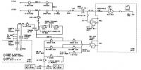
The special feature of generator protection is that different switching devices have to be activated depending on the fault. The number is basically determined by the system/plant concept. As a rule, most of the switching devices need to be actuated in the larger units. Special tripping is used in hydro-electric power stations. Fig. 6 shows the basic concepts. On one side there are the switching devices to be actuated and on the other side the connected protection functions.
The tripping program or tripping concept depends on the recommendations/experiences and the operating conditions. There are two opposing philosophies. The tripping program is determined individually by a tripping matrix (a software matrix in digital technology) and the switching devices are activated directly. The other (American-influenced) variant reduces the tripping to two programs, e.g. exclusive shutdown of the generator and shutdown of the power station unit. Lockout relays are used to control the switching devices. The protection needs only a few trip contacts.
Protection function scope
Numerous protection functions are necessary for reliable protection of electrical generators. The scope and the combination are determined by various factors such as generator size, operating principle, system design, availability requirements, experiences and philosophies. This automatically leads to a multi-functionality which can be controlled excellently by numerical technology.
Protection functions
All protection functions required for the stand-alone protection of generators, power transformers and feeders are available. The system therefore replaces several relays of a conventional protection scheme for such power system equipment. The desired protection functions to suit the particular application can simply be selected from a comprehensive library using the personal computer. No knowledge of computer programming is required. All setting ranges are extremely wide to make the protection functions suitable for a multitude of applications. The following main parameters can be set:
- Allocation of processing units
- Input channel or channels
- Pick-up setting
- Time delay
- Definition of the operating characteristic
- Tripping logic
- Control signal logic.
Setting a corresponding parameter enables the protection functions to be “connected” to particular input channels. Digital input and output signals can also be internally combined logically:
- The tripping outputs of each protection function can be assigned to channels of the tripping auxiliary relay assembly in a manner corresponding to a matrix.
- The pick-up and tripping signals can be assigned to the channels of the signaling auxiliary relay assembly.
- Provision is available for blocking each protection function with a digital signal (e.g. digital inputs or by using the tripping signal of another protection function).
- External signals applied to the digital inputs can be processed in any desired fashion.
- Digital signals can be combined to perform logical functions e.g. external enabling or blocking signals with the output signals of an internal protection function and then used to block one of the other protection functions. [Reference -1 ]
Digital Generator Protection Implementation
The upgrading of existing generator protection schemes with Digital Generator Protection equipment offer the owner of installed generation equipment several unique advantages. These include more complete machine protection, diagnostics capabilities for greater productivity and maintenance optimization, life extension with minimal implementation, and the operational advantages of sequence of events, present values and communications capabilities.
With these additional capabilities avoidance and/or reduction of forced outage time more than justify the retrofit costs. In older installations the electromechanical relays that have been in service for many years are approaching their end of life due to insulation deterioration. Replacement of these relays with new electromechanical or analog relays would not be as cost effective as implementing a digital system. [Reference 2]
The following areas are examined to illustrate the benefits realized by retrofitting existing generator protection schemes with the digital generator protection systems. The Digital Generator Protection System (DGP) is used as an example to illustrate the benefits in the discussions that follow.
- More complete machine protection.
- Self-diagnostics and testing for maintenance optimization.
- Sequence of events, oscillography, present values, and communications.
- Cost savings based on improved productivity and reduced unit outages.
- Additional considerations
The main objective is to improve the protection, provide better maintenance of the protection system through self tests, and predictive maintenance. Each of these aspects brings an important benefit to the user which will be discussed individually. [Reference 3]
Hardware
The protecting equipment comprises two main assemblies which are physically separated from each other and linked by standard prefabricated screened cables:
- Interfaces to the primary system (CTs, PTs and auxiliary relays), which provide DC isolation and a barrier to electromagnetic interference.
- Parallel bus and associated electronic units (e.g. analog inputs and data processors/ for signal conditioning and processing. The complete protection scheme comprises relatively few hardware modules allowing subsequent expansion of electronic units and the interfaces.
Excellent electromagnetic compatibility has been achieved through careful attention to physical separation of the interfaces from the signal processing units. All hardware can be accommodated in one cubicle, which provides a further screen against induced interference and affords physical protection against dust, etc. The protector has a limited number of I/Os but equipped with the same SW library as the Classic system. [Reference 4]
Other protection relays for functions which are not part of the protector may be installed in the cubicle and correspondingly inter-wired with protector. [Reference 5]
Trip Circuit Monitor
The trip circuit monitor consists of DC voltage and current monitors. Under normal condition, DC voltage across the trip contacts is continuously monitored. If the DC voltage becomes virtually zero, then the trip circuit has “failed open”. A non-critical alarm is generated when the self test feature detects this condition.
When the digital system issues a trip, DC current through each of the appropriate trip contacts is monitored. The trip relay is sealed-in, as long as the current is flowing, to protect the contact. A minimum current of 150 milli-amperes is required for this circuit to recognize the trip current.
Status of the trip current flow, following issuance of any trip, is logged in the sequence of events. Benefits to the User:
- Recognizes and alerts of an open trip circuit.
- Checks the trip circuit integrity when breaker and lockout relay are tripped. [Reference 6]
Conclusion:
Digital protection systems are worth consideration based on the above mentioned justification to help meet the objectives of the Condition Assessment Program. This especially applies to larger units where forced outage time is extremely costly to its owners. Additionally, with many older units’ protection systems approaching their end of life due to insulation degradation the present is an appropriate time to consider an upgrade to a digital generator protection system.
[1] [Reference from Gabriel Benmouyal, Serge Barceloux, and Rolland Pelletier, “Field experience with a digital relay for synchronous generators,” IEEE Transactions on Power Delivery, vol. 7, no. 4, October 1992.]
[2] [Reference from “Protective Relays Applications Guide,” The English Electric Company Limited, Relay Division, Stafford, 1975]
[3] [Reference from C. J. Mozina, IEEE Tutorial on the Protection of Synchronous Generators, IEEE]
[4] [Reference from M. S. Sachdev (Coordinator) Microprocessor Relays and Protections Systems, IEEE Tutorial Course Text, Power Engineering Society Special Publ. No.88 EH0269-1-PWR, IEEE, Piscatway, NJ, USA, 1988]
[5] [Below this figure reference from H. Tao and I. F. Morrison, “Digital winding protection for large generators,” J. Electr. Electron. Eng. Aust., 3 (1983), 316-321.]
[6] [Reference from M. S. Sachdev and D. W. Wind, “Generator differential protection using a hybrid computer,” IEEE Trans. Power Apparatus System, PAS-92 (1973) 2063-2072.]
Some are parts: